l
Normal Operation
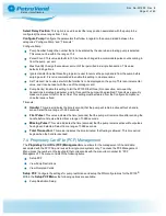
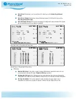
: By placing the switches in the “off” position, relays are energized by the fuel-site
controller.
l
Manual Override
: By placing the switches in the “on” position, relays are energized by the PCM,
which allows pumps to fuel without fuel-site controller control.
Pulser Type (SW 1, Position 3)
: This setting must match the electrical output of the pulser attached. The
PCM supports two types of pulsers:
l
Active
: Pulsers supply a low-voltage signal to the PCM board.
l
Passive
: Pulsers either contain switch contacts or have “open collector” transistor outputs.
NOTE:
This setting applies to the pulsers for both pump positions of the PCM; therefore, both
pulsers must be of the same type.
Pulser Filter (SW 1, Position 4)
: Set to match the type of pulser attached. Mechanical pulsers cannot
count as fast as electronic ones and will generate more electrical noise. Setting the Pulser Filter to
“Mechanical” will filter the input signal.
l
Electronic
: Pulsers typically have shutter wheels and optical detectors.
l
Mechanical
: Pulsers have switches that open and close with each pulse.
NOTE:
This setting applies to the pulsers for both pump positions of the PCM; therefore, both
pulsers must be of the same type.
In-Use Sense (SW 1, Position 5)
: Set based on how the pump is wired to inform the PCM that the pump is
authorized. The PCM is capable of two types of In-Use sense.
l
Voltage Sense
: The most common method, Voltage Sense uses a line-voltage return wire from the
solenoid valve or pump motor wired to the “In Use” terminal on the high-voltage side of the PCM.
l
Handle Sense
: The alternate method, Handle Sense uses a contact closure input wired to the “Flow”
terminal on the low-voltage side of the PCM.
NOTE:
The setting applies to both pump positions of the PCM; therefore, both pumps' In-Use
sense must be the same.
Doc. No.: M1900 Rev.: 8
Page 27 of 65

