background image

3-17

ZUV

User’s Manual

Sect

ion 3

SETUP

Section 3

Setting/Executing Power Tuning

Correcting to a reference value

Tune the controller to the currently set reference value. 

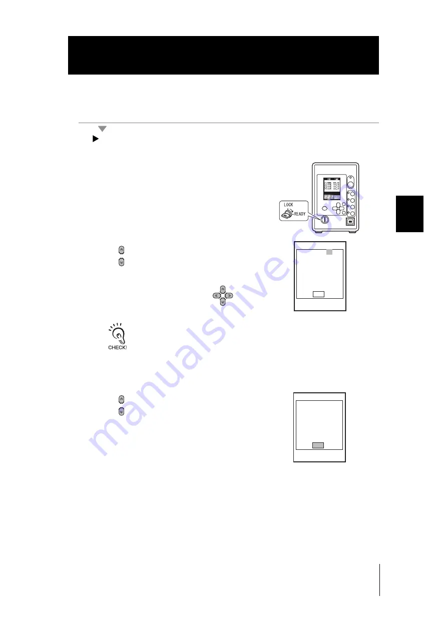
LOCK mode-[TOOL]-[POWER TUNING]-[ON]-[EXECUTE]

1.

Turn the key switch to READY. 

2.

Move the cursor to [CHANNEL] using the

 keys, and press the SET key. 

3.

Set a target channel using the 

 keys,

and press the SET key. 

Change the numeric values and number of

digits by using the 


 UP/DOWN keys and

the 


 L/R keys, respectively. 

4.

Move the cursor to [EXE] using the

 keys, and press the SET key. 

EXECUTE       
CHANNEL:[01]CH

          EXE

EXECUTE       
CHANNEL:[01]CH

          EXE

Summary of Contents for ZUV Series

Page 1: ...Smart Curing System User s Manual Cat No Z281 E1 02 ZUV Series Mega Power Type...

Page 2: ...quired for using the ZUV When using the ZUV be sure to observe the following The ZUV must be operated by personnel knowledgeable in electrical engineering To ensure correct use please read this manual...

Page 3: ...5 Introduction Section 1 Section 2 Section 3 Section 4 Section 5 Terms and Conditions Agreement OVERVIEW INSTALLATION AND CONNECTION ZUV BASIC OPERATION SETUP CONNECTING TO EXTERNAL DEVICES APPENDIX...

Page 4: ...lace in the form originally shipped with Buyer responsible for labor charges for removal or replacement thereof the non complying Product ii repair the non complying Product or iii repay or credit Buy...

Page 5: ...itability of the Product in combination with the end product machine system or other application or use Buyer shall be solely responsible for determining appropriateness of the particular Product with...

Page 6: ...e However some specifications of the Product may be changed without any notice When in doubt special part numbers may be assigned to fix or establish key specifications for your application Please con...

Page 7: ...y or may result in serious injury or death Additionally there may be significant property damage Indicates a potentially hazardous situation which if not avoided may result in minor or moderate injury...

Page 8: ...look directly at or allow your skin to be exposed to the ultraviolet light To prevent exposure to ultraviolet light never look into the ultraviolet light Workers should wear protective goggles and equ...

Page 9: ...in the same duct may cause induction resulting in malfunction or damage Should you notice any abnormalities such as smoke abnormal heat of the product surface and or any foul odor immediately stop use...

Page 10: ...ny other opening Doing so may cause a fire or electric shock Do not install multiple controllers close to others or do not pile them up Doing so may cause a fire or breakdown of the product If some na...

Page 11: ...4 3 When using a DC power supply make sure that the power source is grounded When using a DC power supply observe the following points When using a commercially available switching regulator make sure...

Page 12: ...et channel on the controller If the target channel is not initialized the information cumulative irradiation energy power tuning data of the head before replacement may still remain and prevent normal...

Page 13: ...set at the rate when the maximum power setting is 100 Range 0 to 100 by 1 step Default value 100 Setting Description TIME Set the Irradiation Time Range 000 0 to 999 9 S Default value 999 9 S Setting...

Page 14: ...dow dialog boxes and other GUI elements displayed on the PC are indicated enclosed by brackets Visual Aids Indicates points that are important to ensure full product performance such as operational pr...

Page 15: ...LATION AND CONNECTION 1 1 Basic Configuration 1 2 Part Names and Functions 1 3 Controller 1 3 Head 1 4 Installation Connection 1 5 Before Installation and Connection 1 5 Installing the Controller 1 5...

Page 16: ...ation Log Data 3 18 Setting Cumulative Alarms 3 19 Setting the System Environment 3 20 Setting Passwords 3 20 Setting the Buzzer Function 3 21 Changing the Display Language 3 21 Setting the I O Signal...

Page 17: ...termeasures 5 3 Q A 5 4 Maintenance of the Head 5 4 Cleaning the Lens Unit 5 4 Replacing the Lens Unit 5 5 Specifications and External Dimensions 5 6 Controller 5 6 Requirements from Regulations and S...

Page 18: ...16 ZUV User s manual CONTENTS Introduction CONTENTS MEMO...

Page 19: ...e c t i o n 1 OVERVIEW INSTALLATION AND CONNECTION Basic Configuration 1 2 Part Names and Functions 1 3 Controller 1 3 Head 1 4 Installation Connection 1 5 Before Installation and Connection 1 5 Insta...

Page 20: ...ammable controller Programmable controller Personal computer Personal computer Foot switch External I O RS 232C cable USB cable Controller Head Power supply Select AC or DC power supply AC power suppl...

Page 21: ...channel corresponding to the connected head lights 5 USB port Connect the USB cable to the USB port to connect to a personal computer 6 SET key Selects and applies items when they are being set 7 Key...

Page 22: ...3 Power supply switch Switches the main power supply ON OFF The ON OFF direction differs between the AC power supply and the DC power supply Check the ON OFF direction printed on the main unit 4 AC a...

Page 23: ...e beginning of this manual and check the installation site Power supply Before installing and connecting the controller be sure to turn it OFF Also read Precautions for Safe Use and Precautions for Co...

Page 24: ...is outside the specifications Other lens units cannot be installed on head unit ZUV H40M since a fixed type exclusive lens is attached Never look directly at or allow your skin to be exposed to the u...

Page 25: ...acket supplied with the head 1 Insert the head into the mounting bracket 2 Fix the head to the mounting bracket Screws M3 x 2 Tightening torque 0 9 N m or more to 1 5 N m or less Be sure to use the sc...

Page 26: ...troller rear by aligning the female and male pins of each side of the connectors Connecting the AC Adapter 1 Connect the AC power supply cable to the AC adapter jack on the controller rear The DC powe...

Page 27: ...2 ZUV BASIC OPERATION Starting Up and Shutting Down 2 2 Let s Try Irradiation 2 4 Irradiating at Constant Power 2 5 Creating Irradiation Patterns for Irradiation 2 7 Operating Modes 2 11 Function Sett...

Page 28: ...nly at initial startup When the password function is enabled the password must be entered p 2 11 3 Insert the key in the key switch on the controller front and turn it to the READY position when the L...

Page 29: ...itched to the READY mode without saving the setting data using the MENU key The save confirmation message is displayed only when the settings have been changed Otherwise it is not displayed 2 Move the...

Page 30: ...ion or pattern irradiation Confirmation of Installation and Connection Starting Up and Shutting Down Installation Connection Starting Up Setting the Irradiation Power and Time Irradiating UV Light Irr...

Page 31: ...is 100 Setting the irradiation mode 1 Set the irradiation mode in the LOCK mode top menu When the ZUV is in the READY mode turn the key switch to the LOCK position to switch to the LOCK mode Check to...

Page 32: ...ve the settings and turn the key switch to the READY position to switch to the READY mode The save confirmation message is displayed when the mode is switched to the READY mode without saving the sett...

Page 33: ...et the pattern in the LOCK mode top menu When the ZUV is in the READY mode turn the key switch to the LOCK position to switch to the LOCK mode Check to see if the LOCK mode setting menu is displayed o...

Page 34: ...setting is complete is selected To change and delete the screen display select CORRECT and CLEAR respectively 6 Set the irradiation time s and power for the respective step using the keys and the SET...

Page 35: ...and press the SET key 10 Move the cursor to PATTERN using the keys and press the SET key 11 Move the cursor to xx using the keys and press the SET key 12 Select a pattern using the keys and press the...

Page 36: ...hanged Otherwise it is not displayed 15 Pressing the button starts UV light irradiation The UV ON indicator lights up during irradiation and the irradiation conditions are displayed on the LCD screen...

Page 37: ...e LOCK mode or to the adjustment mode in the intensity power adjustment screen in the READY mode Setting passwords p 3 20 Entering passwords 1 The password entry field is displayed on screen 2 Move th...

Page 38: ...or to OK using the key and press the SET key The password lock is canceled and the display returns to the LOCK mode top screen If the password is wrong the message PASSWORD IS DIFFERENT is displayed I...

Page 39: ...diation Copying Irradiation Conditions p 3 5 p 3 6 p 3 9 This menu sets control from external devices p 4 2 This menu sets banks Switching Banks Copying Banks Clearing Banks Enabling Bank Switching In...

Page 40: ...ge Setting the I O Signal Conditions Initializing Settings Data Checking System Information p 3 22 p 3 21 p 3 21 p 3 22 p 3 22 This menu sets changes passwords p 3 20 This menu sets the buzzer volume...

Page 41: ...ic Detail Display 1CH UV LVL Cumulative Energy List Display CUMULATIVE CHANGE DISP Irradiation Power Adjustment displayed only during fixed irradiation Irradiation Conditions List Display POWER TIME C...

Page 42: ...d and the mode changes to the adjustment mode When the password function is enabled the password must be entered p 2 11 Clicking the CAN cancel button at the password entry field returns the mode to t...

Page 43: ...LIGHT Irradiation in progress OFF Irradiation setting OFF The currently set irradiation pattern is displayed in graph form Irradiation progress can be checked by color Green Irradiation not started R...

Page 44: ...2 18 Section 2 ZUV BASIC OPERATION ZUV User s Manual Section 2 Operating Modes MEMO...

Page 45: ...Banks 3 12 Copying Banks 3 12 Clearing Banks 3 12 Enabling Bank Switching Input 3 13 Setting Executing Power Tuning 3 14 Displaying Irradiation Log Data 3 18 Setting Cumulative Alarms 3 19 Setting the...

Page 46: ...hannel p 3 9 PATTERN EDIT Patterns 01 to 16 When no pattern is set STEP LINEAR When the pattern setting is completed CORRECT CLEAR p 3 6 I O CONTROL ALL CH ALL CH INDIVIDUALLY p 4 2 TERMINAL IN SWITCH...

Page 47: ...password is set to ON BUZZER ON OFF ON p 3 21 LANGUAGE JAPANESE ENGLISH p 3 21 OPTION LIGHT OFF TIME TIME INPUT p 3 21 LOG DATA OFF OFF ON p 3 21 ALL CLEAR SYSTEM DATA Initializes controller settings...

Page 48: ...tion is not performed to OFF in the LOCK mode by selecting CH SET and then selecting each of the channels from 1CH to 4CH Continuous irradiation of UV light for a certain time at constant irradiation...

Page 49: ...de p 2 16 Selecting preset time irradiation unlimited irradiation LOCK mode CH SET 1CH to 4CH LIGNT TIME For details on the settings see Section 2 Let s Try Irradiation p 2 4 Setting value Description...

Page 50: ...P Sets the irradiation power and time in units of steps Interval irradiation can also be set by setting just a time with power set to 0 Range Irradiation power 0 to 100 in 1 steps Total irradiation ti...

Page 51: ...1 Move the cursor to the target pattern using the keys and press the key 2 Select characters using the keys and press the SET key Up to eight characters can be set 3 Move the cursor to SET using the...

Page 52: ...eady have been prepared in advance Creating patterns p 3 6 LOCK mode CH SET 1CH to 4CH PATTERN Changing patterns The content of a set pattern can be changed LOCK mode CH SET PATTERN EDIT PATTERN 1 to...

Page 53: ...3 Move the cursor to EXE using the keys and press the SET key Single copy LOCK mode CH SET CH COPY SINGLE COPY 1 Move the cursor to the copy source using the keys and press the SET key 2 Set a channe...

Page 54: ...ns 4 Set a channel using the keys and press the SET key Change the numeric values and number of digits by using the UP DOWN keys and the L R keys respectively 5 Move the cursor to EXE using the keys a...

Page 55: ...ation conditions of the respective channel are stored in the bank the setting after CH SET BANK2 CH1 CH2 CH3 CH4 Pattern1 Pattern2 Pattern3 Pattern16 Pattern3 Constant irradiation Constant irradiation...

Page 56: ...Copy the settings of a selected bank to the current bank LOCK mode BANK COPY Clearing Banks Initialize the content of a bank Settings made by SYSTEM or I O are not initialized LOCK mode BANK CLEAR Se...

Page 57: ...K TERMINAL Setting value Description OFF Disables bank switching input default value Be sure to set bank switching input to OFF unless the bank is changed using the I O terminal ON Enables bank switch...

Page 58: ...ing the UV luxmeter When setting for power tuning the voltage output terminal of a commercially available UV luxmeter must be connected to the I O terminal block analog input I O terminal block p 4 3...

Page 59: ...disabled The irradiation intensity at the same irradiation power is higher than that when power tuning is set to ON default value When OFF is selected the power tuning reference value that was set whe...

Page 60: ...ch to READY 2 Move the cursor to CHANNEL using the keys and press the SET key 3 Set a target channel using the keys and press the SET key Change the numeric values and number of digits by using the UP...

Page 61: ...UNING ON EXECUTE 1 Turn the key switch to READY 2 Move the cursor to CHANNEL using the keys and press the SET key 3 Set a target channel using the keys and press the SET key Change the numeric values...

Page 62: ...mode TOOL LOG DATA Loading log data to a personal computer Irradiation log data saved on the controller can also be saved to a personal computer Connect the controller to a personal computer by the US...

Page 63: ...o 4CH ON OFF Setting of cumulative energy is enabled only in the READY mode Irradiated energy is not accumulated in the LOCK mode since irradiation is not performed When LOCK mode SYSTEM OPTION LOG DA...

Page 64: ...re displayed on a white background 2 Change the numerical value using the keys and the digit using the keys enter all four digits and press the SET key to apply the setting 3 Move the cursor to OK usi...

Page 65: ...ON LOG DATA Timing charts p 4 7 Setting value Description OFF Sets the buzzer volume to OFF ON Sets the buzzer volume to ON default value Setting value Description JAPANESE Displays menus in Japanese...

Page 66: ...ng the Irradiation Buttons Disable the EMISSION button and CH button LOCK mode SYSTEM BUTTON LOCK Setting value Description SYSTEM DATA Initializes the bank and system setting data HEAD DATA Cumulativ...

Page 67: ...TEM DISPLAY COLOR Setting value Description ON Sets the Eco mode The Eco screen darkens when three minutes continue without any operation default value OFF Cancels the Eco mode setting Setting value D...

Page 68: ...3 24 Section 3 SETUP ZUV User s Manual Section 3 Setting the System Environment MEMO...

Page 69: ...4 CONNECTING TO EXTERNAL DEVICES Connection by an I O Terminal Block 4 2 Connection and Communication Settings 4 2 Timing Charts 4 6 Connection by USB RS 232C 4 9 Connection and Communication Settings...

Page 70: ...nce Selecting ALL CH controls irradiation start stop of all channels using the signal input TRG1 to CH1 default value INDIVIDUALLY individual control Select INDIVIDUALLY to control irradiation start s...

Page 71: ...nput 0 to 5V analog input 1 9 TRG4 Input UV irradiation start stop input CH4 2 AIN2 Input Unused 10 BANK0 Input Bank switching input 0 3 AIN3 Input Unused 11 BANK1 Input Bank switching input 1 4 AIN4...

Page 72: ...g output GND of the external power measurement device when using the power tuning function 6 7 8 9 UV irradiation start stop input This is the UV light irradiation start stop trigger Batch control CH1...

Page 73: ...ake sure that the connection is made to the exclusive GND 32 Bank No BANK3 terminal 13 BANK2 terminal 12 BANK1 terminal 11 BANK0 terminal 10 1 OFF OFF OFF OFF 2 OFF OFF OFF ON 3 OFF OFF ON OFF 4 OFF O...

Page 74: ...ll channels turns ON after irradiation of all channels on the irradiation target other than OFF ends The ready output signal is always OFF for channels whose irradiation setting is OFF The response ti...

Page 75: ...tops the irradiation of each of the channels from 1 to 4 The input time is 40 ms and 120 ms when SWITCH and CONTACT are set respectively Irradiation starts when the ready output of the target channel...

Page 76: ...pt input signal to give priority to for trigger signal input When priority is set to time When priority is set to interrupt input signal Setting trigger signal input priority conditions p 3 21 TRG1 ON...

Page 77: ...connection 1 Plug one end of the USB cable into the USB port of the controller 2 Plug the other end of the USB cable into the USB port of the external device Setting the communication specifications...

Page 78: ...ion specifications Set the RS 232C communications specifications Match the communication specifications of the ZUV to those of the external device LOCK mode SYSTEM COMM PORT Setting value Range DATA B...

Page 79: ...n onwards the USB driver is automatically recognized and does not need to be re installed To install the USB driver log on as an Administrator or a user with system access rights The error message Fai...

Page 80: ...e Next button 4 Select the Search for a suitable driver for my device recommended radio button and click the Next button 5 Select the CD ROM drives checkbox and click the Next button In the event that...

Page 81: ...Make sure that the suitable driver has been detected and click the Next button Installation begins When installation completes the completion message is displayed 7 Click the Finish button The same s...

Page 82: ...aves bank data SYSLOAD Loads system data p 4 21 SYSSAVE Saves system data PATNGET Obtains irradiation patterns p 4 22 PATNSET Sets irradiation patterns p 4 23 PNAMEGET Obtains irradiation pattern name...

Page 83: ...ssfully executed In the event that a command is not executed successfully or the command is not set properly A delimiter which is determined according to the communication condition settings is attach...

Page 84: ...is set use the emergency stop input on the terminal block 1 Parameter description The following parameter can be set by the START and STOP commands 2 Command response examples The following shows an e...

Page 85: ...Command response examples The following shows an example of this command The following shows an example of a response to this command Each line is separated by a delimiter BANKGET Bank No OK Paramete...

Page 86: ...Command response examples The following shows an example of this command The following shows an example of a response to this command BANKSET Switch destination bank No OK Parameter Setting Range Outp...

Page 87: ...the LOCK mode to the READY mode The save confirmation message is displayed The save confirmation message is displayed only when the settings have been changed Otherwise it is not displayed 1 Paramete...

Page 88: ...ollowing parameter can be set by the BANKLOAD and BANKSAVE commands 2 Command response examples The following shows an example of this command The following shows an example of a response to this comm...

Page 89: ...The OK response is returned upon successful completion of send receive The language setting cannot be loaded by the SYSLOAD command 1 Parameter description No parameters are provided for the SYSLOAD a...

Page 90: ...e 1 Linear type STEP xx xx 1 to 16 level 0 to 100 STEP xx xx 1 to 16 time 0 to 9999 0 1s PATNGET 5 Irradiation pattern 5 settings are obtained PATNGET 6 Irradiation pattern 6 settings are obtained 1 1...

Page 91: ...me STEP2 level STEP2 time STEP16 level STEP16 time OK Parameter Setting Range Output Range Pattern No mandatory 1 to 16 Type mandatory 0 Step type 1 Linear type STEP xx xx 1 to 16 level 0 to 100 STEP...

Page 92: ...wing shows an example of this command The following shows an example of a response to this command Each line is separated by a delimiter PNAMEGET Pattern No Pattern name OK Parameter Setting Range Out...

Page 93: ...following shows an example of this command The following shows an example of a response to this command PNAMESET Pattern No Pattern name OK Parameter Setting Range Output Range Pattern No 1 to 16 Pat...

Page 94: ...eter No 32 Irradiation mode 33 Irradiation power 34 Irradiation time 35 Irradiation pattern 38 Irradiation time and type Obtained data When the irradiation mode is set 0 OFF 1 CONSTANT 2 PATTERN When...

Page 95: ...annel 1 1 Channel 2 2 Channel 3 3 Channel 4 Parameter No 32 Irradiation mode 33 Irradiation power 34 Irradiation time 35 Irradiation pattern 38 Irradiation time and type Write data When setting irradi...

Page 96: ...Irradiation start time Irradiation end time OK Parameter Setting Range Output Range Number of obtained data 1 to 100 Target channel 1 to 4 Irradiation start time hh mm dd 00 00 00 to 23 59 59 Irradia...

Page 97: ...and obtained by the ACCUMGET command 2 Command response examples The following shows an example of this command The following shows an example of a response to this command Each line is separated by...

Page 98: ...djustment Display 2 Channel Specific Detail Display 3 Cumulative Energy List Display 1 LANGUAGE 0 JAPANESE 1 ENGLISH 2 Buzzer volume 0 OFF 1 ON 3 ECO display 0 OFF 1 ON 4 Menu color 0 MARINE BLUE 1 GR...

Page 99: ...miter 0 CR 1 LF 2 CR LF 13 EMISSION button lock 0 OFF 1 ON 14 Channel irradiation button lock 0 OFF 1 ON SYSGET 0 The READY mode display data No is obtained SYSGET 2 The buzzer volume is obtained 1 RE...

Page 100: ...ustment Display 2 Channel Specific Detail Display 3 Cumulative Energy List Display 1 LANGUAGE 0 JAPANESE 1 ENGLISH 2 Buzzer volume 0 OFF 1 ON 3 ECO display 0 OFF 1 ON 4 Menu color 0 MARINE BLUE 1 GRAS...

Page 101: ...sponse to this command 12 RS 232C USB delimiter 0 CR 1 LF 2 CR LF 13 EMISSION button lock 0 OFF 1 ON 14 Channel irradiation button lock 0 OFF 1 ON SYSSET 0 1 The Irradiation Power Adjustment Display i...

Page 102: ...example of a response to this command CALIBGET Channel No CALIBSET Channel No OK Parameter Setting Range Output Range Channel No 1 Channel 1 2 Channel 2 3 Channel 3 4 Channel 4 CALIBGET 1 Setting of t...

Page 103: ...e following shows an example of this command The following shows an example of a response to this command Each line is separated by a delimiter VERGET Software version OK Parameter Setting Range Outpu...

Page 104: ...ter can be set by the HDATACLR command 2 Command response examples The following shows an example of this command The following shows an example of a response to this command HDATACLR Channel No OK Pa...

Page 105: ...or performing communications by non procedural commands on the Windows standard tool Hyper Terminal 1 Start up Hyper Terminal Hyper Terminal is provided under the Communication folder which you can ac...

Page 106: ...CONNECTING TO EXTERNAL DEVICES ZUV User s Manual Section 4 Connection by USB RS 232C 3 Set the communication conditions In the case of the USB connection set Bits per second to 115200 4 Hyper Terminal...

Page 107: ...n by USB RS 232C 2 Set items such as echoback for easier understanding of command transactions 1 Select Properties to open the ZUV Properties dialog box 2 Select the Settings tab and select ASCII Setu...

Page 108: ...munication conditions 1 Match the LOCK mode SYSTEM COM settings to the settings on the personal computer 2 Switch the controller to the READY mode 4 Execute non procedural communications 1 Enter a com...

Page 109: ...enance of the Head 5 4 Cleaning the Lens Unit 5 4 Replacing the Lens Unit 5 5 Specifications and External Dimensions 5 6 Controller 5 6 Requirements from Regulations and Standards 5 8 Summary of Requi...

Page 110: ...t if pressing any key automatically returns to the original brightness The brightness is maintained when the Eco mode setting is canceled Note however that the life of the LCD backlight is shortened S...

Page 111: ...RD WARE KEY TO LOCK The power supply was turned ON when the key switch was in the READY position Change the position of the key switch to LOCK CHANGE HARD WARE KEY TO READY The key switch is in the LO...

Page 112: ...using a soft cloth moistened with ethanol Care should be taken for the items below when cleaning the lens because cleaning may scratch the lens surface or remove its protective coating Do not use any...

Page 113: ...rn the lens unit in the direction of the arrow to take the lens unit out from the head unit 2 Turn the replacement lens unit in the direction of the arrow to install it on the head unit Tightening tor...

Page 114: ...ction 5 Specifications and External Dimensions Specifications and External Dimensions Controller ZUV C30H 63 5 7 8 23 4 23 146 3 5 9 7 6 12 7 12 7 21 12 6 21 5 30 8 13 1 10 1 36 57 4 106 6 81 6 56 6 3...

Page 115: ...pply voltage Select AC or DC power supply AC power supply 100 to 240 VAC 10 50 60 Hz AC adapter supplied DC power supply 24 VDC 10 supplied from the terminal block on rear of unit Current consumption...

Page 116: ...e panel until accessible emission values are below that for Class 3R Designed to prevent removal of the panel until accessible emission values are below that for Class 3B Remote control Not required P...

Page 117: ...1 1993 Section 2 Wavelength range label Required for certain wavelength ranges LED label Make required word substitutions for LED products User information Operation manuals must contain instructions...

Page 118: ...le emission Required for non visi ble emis sion Required Remote interlock Not required Connect to room or door circuits Key control Not required Remove key when not in use Beam attenuator Not required...

Page 119: ...from 400 nm to 700 nm Eye pro tection is normally afforded by aversion responses including the blink reflex Class 3A Lasers which are safe for viewing with the unaided eye For laser emitting in the wa...

Page 120: ...5 12 Section 5 APPENDIX ZUV User s Manual Section 5 Requirements from Regulations and Standards...

Page 121: ...er 3 14 Constant irradiation 2 5 3 5 Control keys 1 3 Controller Installation 1 5 Part Names 1 3 Shutdown 2 3 Specifications external dimensions 5 6 Startup 2 2 CORRECT 3 8 Cumulative Alarm 3 19 Cumul...

Page 122: ...ng 3 8 Creating 3 6 Pattern name setting 3 7 Selecting 3 8 PNAMEGET command 4 24 PNAMESET command 4 25 Power supply switch 1 4 Power Tuning 3 14 R READY mode 2 15 Reference value Correcting 3 17 Setti...

Page 123: ...5 15 ZUV User s Manual Section 5 APPENDIX Section 5 INDEX MEMO...

Page 124: ...d table for BUZZER Page 4 3 Added wire length to figure Page 4 10 Changed model number of recommended part Page 4 16 Added item to CHECK Page 4 22 Removed commas from command response examples Pages 4...

Page 125: ......

Page 126: ...9 U S A Tel 1 847 843 7900 Fax 1 847 843 7787 Contact www ia omron com Kyoto JAPAN OMRON ASIA PACIFIC PTE LTD No 438A Alexandra Road 05 05 08 Lobby 2 Alexandra Technopark Singapore 119967 Tel 65 6835...

Reviews: