background image

Laser Safety

183

ZG User’s Manual

 5 

APPENDICES

Laser Safety

Various safety standards regarding laser products are stipulated depending on the
country of use.

Take safety measures according to each standard.

Classification

*1

For products exported to the countries other than Japan and Europe, different safety standards are applied 

according to the countries. Check the LED safety regulations and standards of the relevant country.

Label Replacement

Use in the U.S.A.

Products relevant to FDA are supplied with labels that conform to FDA regulations.

When these products are used in the U.S.A., replace the warning label on the sensor
body with the FDA labels (supplied) referring to the figure below. Make sure that the
labels are affixed at the correct locations as indicated.

The ZG Series is intended to be fitted into a system as a terminal device. Follow the
following technical standards when fitting in the device.

* FDA: 21CFR 1040.10 and 1040.11

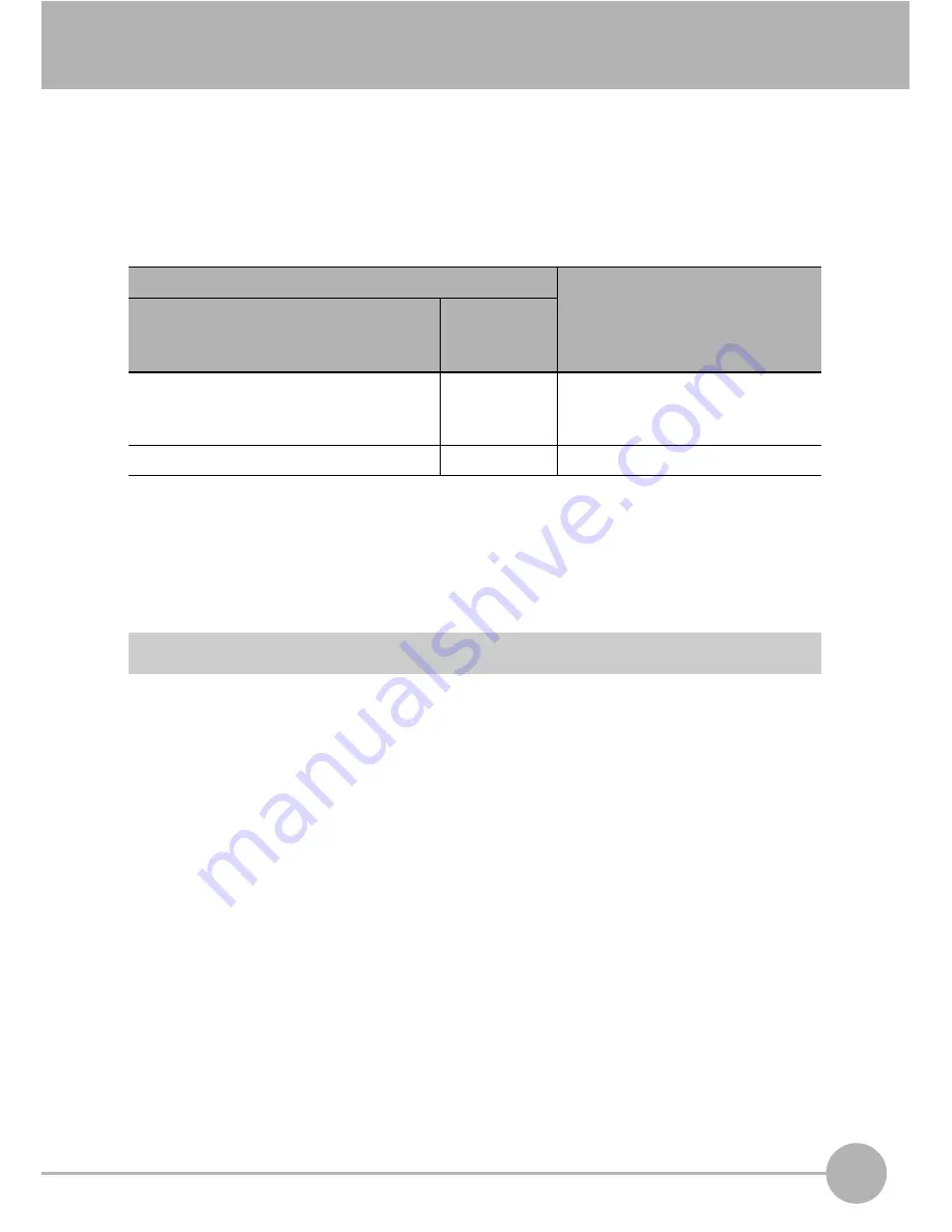
Standards and classification (*1)

Maximum Output of Laser Beam

JIS C 6802 2005 (Japan), 

EN60825/IEC60825-1 (Europe)

FDA 
(the United 
States)

ZG-WDS70/WDS22/WDS8T:  Class 2M Class IIIB

Max. output 5 mW
Max. exposure (when optical 
device is not used) 1 mW

ZG-WDS3T: 

Class 2

Class II

Max. output 1 mW

Summary of Contents for ZG -

Page 1: ...Cat No Z250 E1 02 2D Profile Measuring Sensors Smart Sensor ZG Series User s Manual Cat No Z250 E1 02 ZG Series 2D Profi le Measuring Sensors User s Manual ...

Page 2: ...lectrical engineering To ensure correct use please read this manual thoroughly to deepen your understanding of the product Please keep this manual in a safe place so that it can be referred to whenever necessary How to Switch the Display Language to English Turn the power ON with the MENU key held down This displays the display language selection screen The Controller will start up with the messag...

Page 3: ... 2 3 4 5 User s Manual APPLICATION CONSIDERATIONS Please Read BEFORE USE BASIC OPERATIONS FUNCTION SETTINGS CONNECTION WITH EXTERNAL DEVICE APPENDICES Smart Sensor 2D Profile Measuring Sensors ZG Series ...

Page 4: ...RMINED THAT THE PRODUCTS WILL SUITABLY MEET THE REQUIREMENTS OF THEIR INTENDED USE OMRON DISCLAIMS ALL OTHER WARRANTIES EXPRESS OR IMPLIED LIMITATIONS OF LIABILITY OMRON SHALL NOT BE RESPONSIBLE FOR SPECIAL INDIRECT OR CONSEQUENTIAL DAMAGES LOSS OF PROFITS OR COMMERCIAL LOSS IN ANY WAY CONNECTED WITH THE PRODUCTS WHETHER SUCH CLAIM IS BASED ON CONTRACT WARRANTY NEGLIGENCE OR STRICT LIABILITY In no...

Page 5: ...he following are some examples of applications for which particular attention must be given This is not intended to be an exhaustive list of all possible uses of the products nor is it intended to imply that the uses listed may be suitable for the products Outdoor use uses involving potential chemical contamination or electrical interference or conditions or uses not described in this document Nuc...

Page 6: ...application on your request Please consult with your OMRON representative at any time to confirm actual specifications of purchased products DIMENSIONS AND WEIGHTS Dimensions and weights are nominal and are not to be used for manufacturing purposes even when tolerances are shown ERRORS AND OMISSIONS The information in this document has been carefully checked and is believed to be accurate however ...

Page 7: ...icates general prohibitions for which there is no specific symbol Indicates the possibility of laser radiation Indicates prohibition when there is a risk of minor injury from electrical shock or other source if the product is disassembled This product is not designed or rated for ensuring safety of persons Do not use it for such purposes Never look into the laser beam Doing so continuously will re...

Page 8: ...be short circuited Use the power supply within the rated load High voltage lines and power lines must be wired separately from this product Wiring them together or placing in the same duct may cause induction resulting in malfunction or damage Use the product within the power supply voltage specified by this manual Use a DC power supply with safety measures against high voltage spikes safety extra...

Page 9: ... the FG terminal is grounded If surge currents are present in the power lines connect surge absorbers that suit the operating environment Before turning ON the power after the product is connected make sure that the power supply voltage is correct there are no incorrect connections e g load short circuit and the load current is appropriate Incorrect wiring may result in breakdown of the product Be...

Page 10: ...oft cloth for cleaning lenses moistened with a small amount of alcohol Do not use excessive force to wipe off dust particles Scratches to the filter might cause error 5 Measurement Target The measurement target is a non transparent object The sensor cannot detect the following types of objects accurately materials with extremely small reflectances objects smaller than the beam diameter objects wit...

Page 11: ...indows dialog boxes and other GUI elements displayed on the PC are indicated enclosed by brackets Visual Aids Indicates points that are important to achieve the full product performance such as operational precautions Indicates application procedures Indicates pages where related information can be found Important Note ...

Page 12: ...10 ZG User s Manual MEMO ...

Page 13: ...Data 38 Setup Modes 40 Initializing Controller Settings 41 2 BASIC OPERATIONS Setting Measurement Conditions FUN Mode 44 Checking Adjusting the Measurement Status ADJ Mode 49 Checking Measurement Status 49 Setting the Judgment Value 51 Adjusting the Output Conditions of the Measurement Result 52 Setting Processing during Non measurement 53 Functions Operations Used during Operation RUN Mode 54 Mon...

Page 14: ...ns 90 Setting Conditions When a Parallel Output Unit is Used 95 Setting I O Conditions 96 Setting Serial Output Conditions 98 System Settings 100 Setting the Sensor Installation Status 100 Setting the CCD Mode 103 Setting the RS 232C Communication Specifications 104 Setting the Node No 104 Setting the Sensor Data Loading Method 105 Setting the Number of Digits Past the Decimal Point 105 Setting Ch...

Page 15: ... Measurement Value Acquisition Commands 136 Setting Acquisition Change Commands 139 Backup Restore Commands 141 Utility Commands 145 Parameter List 148 Command Processing Time 153 5 APPENDICES Basic Knowledge for Operation 156 CCD Mode 156 Sensitivity Adjustment and Measurement Operations 158 Specifications and External Dimensions 161 Sensor 161 Controller 169 Accessories 172 Error Messages and Co...

Page 16: ...r s manual Summary of Requirements to User 190 Definitions of Laser Classification 193 Compliance with EC Directives 195 Updating the Firmware 196 INDEX 201 Software Upgrade Information 207 Revision History 208 ...

Page 17: ...1 BEFORE USE BEFORE USE ZG Series 16 Mounting and Connecting Devices 21 Overview of Settings and Measurement 36 ...

Page 18: ...ripheral devices System Configuration Sensor Controller ZG series ZG WDC11 WDC41 PC Smart Monitor ZG exclusive PC software ZG WDS70 ZG WDS22 ZG WDS8T ZG WDS3T Photoelectric sensor etc ZS RPD PARALLEL OUTPUT UNIT RS 232C DATA ZG RPD11 RPD41 Parallel Output Unit Exclusive PC software allows complex setups and verification of measurement values to be performed with ease SmartMonitor ZG and USB cable ...

Page 19: ...onnector cable option For PC ZS XRS2 For PLC PT ZS XPT2 A USB connection allows measurement data to be captured easily on a PC Also the Controller can be controlled from a PC e g switching changing of setup data and input of measurement trigger Measurement values and judgment results can be output at high speed on the parallel interface Measurement values and judgment results can be acquired and t...

Page 20: ...Both indicators are OFF until Controller startup is completed after the power is turned ON Indicator At startup RUN ADJ FUN mode LD OFF in progress LD ON in progress Standby indicator STANDBY OFF ON ON Laser indicator LD ON OFF OFF ON 2 Laser emitter This emits the laser for measurement 3 Laser receiver This receives the laser light reflected from the measurement target 4 Connector This is the con...

Page 21: ...t is NG or an error occurs 2 Laser indicator The laser indicator turns ON while the Sensor is emitting a laser beam 3 Zero Reset indicator The Zero Reset indicator turns ON when the zero reset function is enabled 4 Trigger indicator The Trigger indicator turns ON when a trigger signal is input 5 LCD monitor The LCD monitor displays setup menus and images captured from the Sensor 1 2 3 4 1 5 6 3 Di...

Page 22: ...EXP Expert menu Select this item when making a more detailed setup Name Function 1 Sensor connector This connector connects the Sensor 2 Function extension connector Not used Leave the cover supplied attached to this connector 3 USB port Connect the USB cable MINI B to the USB port to connect to a personal computer 4 RS 232C connector Connect the RS 232C cable exclusive product when you are connec...

Page 23: ...tations Measuring stepped objects Measurement errors can be reduced by installing the Sensor with the line formed by the emission and reception axes parallel to the wall and painting the wall with non reflective black paint Mounting near walls You can minimize the influence caused by vibration of the rotating object and positional shifts by installing the Sensor with the line formed by the emissio...

Page 24: ...asten the Sensor onto the mounting base with M4 screws Tightening torque 1 2 N m For details on the positions of screw holes check the external dimensions in Chapter 5 APPENDICES External dimensions p 163 Mounting position Mount the Sensor according to the following distances and angle Important Mounting for diffuse reflection measurement Emission axis Reception axis 210 mm 19 Measurement target ...

Page 25: ...re not to be used as guaranteed values Measurement center distance Measurement range height Measurement range width Beam diameter 210 mm 30 mm NEAR end 63 mm 300 µm CENTER 70 mm 120 µm FAR end 79 mm 300 µm NEAR end 30 mm CENTER 0 mm FAR end 30 mm Measurement center distance 210 mm Spread angle 10 Angle of intersection 19 Measurement range Irradiation range 63 mm 70 mm 79 mm Measurement range width...

Page 26: ...apter 5 APPENDICES External dimensions p 164 Mounting position Mount the Sensor according to the following distances and angle The default mounting state of the Sensor is for diffuse reflection measurement To set the Sensor for regular reflection measurement change the Sensor mounting setting Setting the Sensor Installation Status p 100 Important Mounting for diffuse reflection measurement Emissio...

Page 27: ... CENTER 22 mm 60 µm FAR end 24 mm 220 µm Measurement center distance Measurement range height Measurement range width Beam diameter 94 mm 10 mm NEAR end 20 mm 220 µm CENTER 22 mm 60 µm FAR end 24 mm 220 µm NEAR end 12 mm CENTER 0 mm FAR end 12 mm Measurement center distance 100 mm Spread angle 10 Angle of intersection 25 Measurement range Irradiation range 20 mm 22 mm 24 mm Measurement range width...

Page 28: ...Chapter 5 APPENDICES External dimensions p 164 Mounting position Mount the Sensor according to the following distances and angle The default mounting state of the Sensor is for diffuse reflection measurement To set the Sensor for regular reflection measurement change the Sensor mounting setting Setting the Sensor Installation Status p 100 Important Mounting for diffuse reflection measurement Emiss...

Page 29: ...NTER 8 0 mm 30 µm FAR end 8 6 mm 120 µm Measurement center distance Measurement range height Measurement range width Beam diameter 44 mm 2 mm NEAR end 7 9 mm 120 µm CENTER 8 0 mm 30 µm FAR end 8 6 mm 120 µm NEAR end 3 mm CENTER 0 mm FAR end 3 mm Measurement center distance 50 mm Spread angle 10 Angle of intersection 30 Measurement range Irradiation range 7 9 mm 8 0 mm 8 6 mm Measurement range widt...

Page 30: ...hapter 5 APPENDICES External dimensions p 166 Mounting position Mount the Sensor according to the following distances and angle The default mounting state of the Sensor is for diffuse reflection measurement To set the Sensor for diffuse reflection measurement change the Sensor mounting setting Setting the Sensor Installation Status p 100 Important Mounting for regular reflection measurement Emissi...

Page 31: ... mm 40 µm CENTER 3 0 mm 25 µm FAR end 3 1 mm 40 µm Measurement center distance Measurement range height Measurement range width Beam diameter 5 2 mm 0 4 mm NEAR end 2 9 mm 40 µm CENTER 3 0 mm 25 µm FAR end 3 1 mm 40 µm NEAR end 0 5 mm CENTER 0 mm FAR end 0 5 mm Measurement center distance 20 mm Angle of intersection 50 Measurement range Irradiation range 2 9 mm 3 0 mm 3 1 mm Measurement range widt...

Page 32: ...er in the following orientations Do not block the ventilation holes at the top and bottom of the Controller body Doing so will cause heat to build inside and result in a malfunction When the temperature inside the control panel exceeds the ambient temperature of 50 C provide forced air cooling or more space at surrounding areas or improve air circulation to lower the ambient temperature to 50 C or...

Page 33: ...n the I O cable side is locked After mounting the Controller on the DIN track attach the end plates on both sides of the Controller Removing the Controller from the DIN track 1 Pull the hook on the I O cable end of the Controller downwards 2 Lift up the Controller from the I O cable end and remove it from the DIN track 1 2 Important DIN track sold separately PFP 100N 1 m PFP 50N 0 5 m PFP 100N2 1 ...

Page 34: ... Controller 4 Install the Controller with Mount Adapters attached onto the panel from the front 5 Hook the hooks of the mounting fixture onto the two holes of the short Mount Adapters and tighten the screws 6 Make sure that the Controller is firmly fixed on the panel When mounting multiple Controllers on a panel be sure to install the DIN track on the rear side of the Controllers for support Note ...

Page 35: ...ntil it locks in place 3 Connect the Controller s I O cable and power supply If the Controller is turned ON without the Sensor connected the Controller s screen will remain dark and messages cannot be read Before turning the Controller ON connect the Sensor Attaching the Ferrite Cores Attach the ferrite cores supplied to both ends of the Sensor cable and to the Controller s I O cable When attachin...

Page 36: ...s inside the connector All settings on the Controller will be cleared if the Sensor is replaced with a different type Fasten the connector while making sure that it is not subjected to vibration or shock Do not mount the Controller in such a way that a load is steadily applied on the connector for example with tension applied to the cables Important At least 10 mm When wiring do not bend the cable...

Page 37: ...adually The cable connection between the Sensor and the Controller can be extended by using the extension cable sold separately Digital equalizer and Digital equalizer connection cable Attach the ferrite cores supplied to both ends of the extension cable and Digital equalizer connection cable 1 When attaching the ferrite core to both ends of the extension cable pass the cable once through the ferr...

Page 38: ...s mode is for setting the measurement conditions The easy to follow icon based display allows operations to be performed intuitively ADJ mode This mode is for checking the measurement state and setting threshold values and output conditions RUN mode This mode is used for performing actual measurement The measurement information is displayed on the LCD screen ADJ mode RUN mode FUN mode MEAS FUN Top...

Page 39: ...e used to set the measurement conditions Height measurement items are already set as the default so it is possible to know immediately the detection status of the Sensor by setting the operation mode to the RUN mode On the ZG series measurement points in the height and width directions are measured on the vertical Z axis and horizontal X axis axes respectively Measurement values are displayed as n...

Page 40: ...asks 1 to 4 respectively In other words this means that the total of tasks 1 to 4 allow you to judge the shape Data for Change of Device Setup If you register bank data for each individual model you can reduce the time required for changing the device setup as all you need to do is to select different bank data to change the measurement conditions Task 1 Height Width Step Task 2 Task 3 Task 4 Cros...

Page 41: ...number of measurement points that can be set at once is 16 points For this reason eight tasks cannot be set in the case of measurement items that use multiple points For example the maximum number of tasks that can be set when using three points for a single task such as in 3 pt step is five tasks Measurement judgment conditions Profile registration information Setup information of image adjustmen...

Page 42: ...an start measurement immediately EXP mode This mode allows you to set all adjustment functions You can use this mode to execute advanced measurement processing such as measurement of image angle calculation of processing items and selection of characteristic points Switching the mode The STD and EXP modes are switched by the mode switch on the front of the controller Two modes cannot be selected s...

Page 43: ...ted bank No To save the settings back them up to a personal computer before performing initialization Receive System Data SYSSAVE command p 144 Receive Bank Data BANKSAVE command p 142 1 Switch to the FUN mode The top screen is displayed 2 Select System 3 Select INIT 4 Move to YES and press the SET key Important MEAS FUN P1 3 SYS 1 SAVE 2 INIT 3 SENSOR SET 4 CCD MODE SYS INIT CLEAR ALL DATA YES NO...

Page 44: ...Overview of Settings and Measurement 42 ZG User s Manual MEMO ...

Page 45: ...2 BASIC OPERATIONS BASIC OPERATIONS Setting Measurement Conditions FUN Mode 44 Checking Adjusting the Measurement Status ADJ Mode 49 Functions Operations Used during Operation RUN Mode 54 ...

Page 46: ...ment Conditions FUN Mode The following describes the flow of basic setup using as an example 2 pt step Registering profiles 1 Switch to the STD mode 2 Switch to the FUN mode The top screen of the FUN mode is displayed 3 Select MEAS 0 00000 mm LV 320 2PTS 2 BIT2 step 1 MEAS FUN ...

Page 47: ...t Sensor is turned OFF Sensor mounting conditions If the profile is not displayed correctly adjust by IMAGE p 74 If necessary change the Sensor mounting orientation for diffuse reflection measurement or for regular reflection measurement or change the receiving status of the Sensor CCD before setting the measurement conditions Setting the Sensor Installation Status p 100 Setting the CCD Mode p 103...

Page 48: ...lect the measurement item To measure multiple items Simultaneous measurement of up to eight items can be performed To do this repeat steps 2 and 3 Note however that the maximum number of measurement points that can be set at once is 16 points For this reason eight tasks cannot be set in the case of measurement items that use multiple points For example the maximum number of tasks that can be set w...

Page 49: ...on so that the center line overlaps the area that divides the top and bottom of the step When the desired measurement area is enclosed the region in which measurement points are extracted is automatically set If the target region is not displayed by automatic setting select CUSTOM and adjust the region for each individual measurement point step 3 50 000mm 123LINE SET TRIMMING 10 000mm 450LINE SET ...

Page 50: ...ed and the current profile is displayed in the Through mode Check that measurement is being performed correctly When the RUN mode is switched to you will be prompted to save the settings Save the setting data before turning the Smart Sensor OFF The setting data will be cleared if you turn the power OFF without saving it To switch the task display use the UP key DOWN key step 4 109 05210mm LV 1 320...

Page 51: ... monitor The current profile is displayed in the Through mode When multiple tasks are registered switch the profile and display it for each individual task To switch the task display use the UP key DOWN key 109 05210mm LV 1 320 HEIGHT1 BIT1 1JUDGE 2ZERO 3FILTER 4ERROR HEIGHT1 BIT1 MENU VIEW Profile monitor Output condition setup monitor 109 05210mm LV 1 320 HEIGHT1 BIT1 Measurement item Bank No Ta...

Page 52: ...t conditions for the measurement results Setting the Judgment Threshold Value p 51 Setting the Offset Zero Value p 51 Setting the Average Number of Times p 52 Setting Smoothing p 53 Setting Processing during Non measurement p 53 1JUDGE 2ZERO 3FILTER 4ERROR HEIGHT1 BIT1 Measurement item Bank No Task No Output condition ...

Page 53: ...o Reset Offset Value To set a reference value for zero reset to a value other than 0 zero set the offset amount using this function After setting any target value execute a zero reset in the RUN mode Setting Zero Reset p 56 ADJ mode MENU VIEW key ZERO Setting value Description HIGH Sets the HIGH threshold value Range 999 99999 to 999 99999 LOW Sets the LOW threshold value Range 999 99999 to 999 99...

Page 54: ... 1 2 4 8 16 32 64 128 256 Sets the average number of measurements default value 1 To change numerical values use the UP key DOWN key The calculation method for the average values differs according to the measurement trigger and sensitivity adjustment settings Moving average The average value is output from the past N number of results Simple average Measurement is performed for N number of times a...

Page 55: ...fixed sensitivity Setting Processing during Non measurement Set the output methods for when a non measurement state occurs temporarily for example due to insufficient received light amount or the reset input status ADJ mode MENU VIEW key ERROR ERROR Setting value Description OFF LOW MID HIGH Sets the smoothing strength default value LOW The intermediate value of the past measurement values for the...

Page 56: ...ch individual task are displayed as a list as numerical values ECO monitor The measurement cycle and CCD mode are displayed To switch the task display use the UP key DOWN key To switch the display between tasks 1 to 4 and tasks 5 to 8 use the UP key DOWN key 109 05210mm LV 1 320 HEIGHT1 BIT1 B1 T1 HEIGHT1 109 05210mm T2 2PTS 1 109 05210mm T3 T4 B1 XXXXms NORMAL MENU VIEW MENU VIEW MENU VIEW Profil...

Page 57: ...layed To return the display to the normal display press the F2 key again Measurement is stopped while the image is displayed F3 When the F3 key is pressed and held down for 3 seconds or longer the key lock confirmation message is displayed When the key lock function is ON the FUN ADJ RUN modes cannot be switched To cancel the key lock press and hold down the F3 key for 3 seconds or longer F4 Magni...

Page 58: ...e RUN mode the measured value can be reset to 0 at any time during measurement 1 Set the object to be used as the reference in place 2 Press the SET key The Zero Reset indicator lights and the current measured value is registered as 0 zero To cancel a zero reset press and hold the ESC key for 2 seconds or longer Zero reset can also be executed and canceled by an external input A value other than z...

Page 59: ...ile Display A specified area of the profile display can be magnified RUN mode F4 key MGNIFY 50 000mm 123LINE SET MGNIFY 1MGNIFY 2RESET SU HEIGHT1 When the desired region of the profile is enclosed it is displayed magnified While the profile display is magnified SU is displayed at the bottom right of the screen ...

Page 60: ...Functions Operations Used during Operation RUN Mode 58 ZG User s Manual MEMO ...

Page 61: ...3 FUNCTION SETTINGS FUNCTION SETTINGS Measurement Settings 60 Bank Settings 88 I O Settings 90 System Settings 100 ...

Page 62: ...is item measures the height How to adjust the region p 66 Height direction Width direction Other Height 2 pt step 3 pt step Edge position Edge width Angle Cross sectional area Calculation Icon Description Average Measures the average value inside an area Peak Measures the maximum value peak inside an area Bottom Measures the minimum value bottom inside an area Height Height Height Illustration of ...

Page 63: ...sures the step between the average values of P1 and P2 Peak Measures the step between the average value of P1 and the maximum value of P2 Icon Description Average Measures the step between the average values of P1 and P2 Bottom Measures the step between the average value of P1 and the minimum value of P2 2 pt step Step Step 3 pt step Step P2 average P1 average Step P2 peak P1 average Step P1 avera...

Page 64: ... sides P1 P2 as the reference plane Icon Description Average Measures the step between the average value of P3 taking the average values of both sides P1 P2 as the reference plane Bottom Measures the step between the minimum value of P3 taking the average values of both sides P1 P2 as the reference plane Step P3 average P1 average P2 average Step P3 peak P1 average P2 average Step P2 average P1 av...

Page 65: ...t is positioned on the right side inside an area Icon Description Width Measures the width of the protrusions between edges that are extracted inside an area Width Measures the width of the indentations between edges that are extracted inside an area The edge level can be changed in the EXP mode How to change the edge level p 70 Edge position Edge position Width Width Enclose the desired measureme...

Page 66: ...le The average values inside the region are each extracted as points A straight line is drawn between the two extracted points and the angle formed by the intersection between that straight line and the X axis is measured as the angle The angle between the two points is measured taking the average inside the specified region as the measurement points Angle θ P2 P1 Set region P1 to P2 Illustration ...

Page 67: ...ional area is calculated by integrating the distances between each of the measurement points and the bottom face Icon Description Calc Set any equation to perform addition subtraction on the measurement result The equation can be substituted with measurement results obtained by other tasks Allowable equation K mX nY K range 999 99999 to 999 99999 default value 0 00000 m n range 10 0 to 10 0 defaul...

Page 68: ...ing this function when measurement items angle and cross sectional area for which automatic setting cannot be performed are selected FUN mode MEAS SENS TASK1 to 8 CUSTOM REGION 1 Specify the start and end lines of the region P1 Left Right key Moves the cursor SET key Applies the setting ESC key Cancels the setting 2 Specify the start and end lines for the number of regions POINT1 START 0 LINE SET ...

Page 69: ...desired measurement area is enclosed the region in which measurement points are extracted is automatically set When there is a step set so that the center line of the region matches the area that divides the top and bottom of the step When there is an edge set so that the center line of the region matches the edge to be detected Automatic setting can be executed by the same procedure regardless of...

Page 70: ...NIFY 1 Select MGNIFY 2 Adjust the top left of the desired display area by the and keys and press the SET key 3 Adjust the bottom right of the desired display area by the and keys and press the SET key 4 Move to YES and press the SET key 1MGNIFY 2RESET MEAS MGNIFY 50 000mm 123LINE SET MEAS MGNIFY 10 000mm 450LINE SET MEAS MGNIFY SE MEAS MGNIFY MAGNIFY PROFILE YES NO ...

Page 71: ...measured Set this menu item when measuring small unevenness The measurement point setting is enabled only in the EXP mode FUN mode MEAS SENS TASK1 to 8 CUSTOM POINT POINT1 to 2 Setting value Description AVE average Measures the average value inside the line beam PEAK Measures the peak position of the line beam BTM Measures the bottom position of the line beam 1MGNIFY 2RESET MEAS MGNIFY Average Pea...

Page 72: ...ging the edge level Selecting the edge direction Set the edge search direction Setting value Description Edge level Align the line of the edge level with the edge to be detected The range differs according to the CCD mode Standard and high resolution mode 0 to 399 High speed mode 0 to 199 Setting value Description Forward direction The 1st edge from the left in the area is searched for Reverse dir...

Page 73: ...gs below return to the default settings when scaling is set Set these items after scaling settings have been completed Zero reset Measurement items Setup Method Reference 2 pt step 3 pt step edge width Automatic setting one point scaling Measurement is performed once and the correction value for the measurement value is set p 72 Height edge position Automatic setting two point scaling Measurement ...

Page 74: ... in place and press the SET key 2 Input the correction value for the measurement value on the upper section 3 In the case of two point scaling height edge position move the measurement target and repeat steps 1 and 2 to set the 2nd point To change numerical values use the UP key DOWN key and to change the number of digits use the LEFT key RIGHT key MEAS AUTO FIRST POINT SET INPUT CORRECT VALUE MEA...

Page 75: ...s executed So modify these settings as necessary Manual setting is enabled only in the EXP mode FUN mode MEAS SENS TASK1 to 8 SCALE MANUAL Setting value Description SPAN Sets the inclination of the sensor characteristics as a coefficient Range 4 0000 to 4 0000 OFFSET Adds subtracts a fixed value to or from the measured value Range 999 99999 to 999 99999 4 0000 mm 4 0000 Measurement value Displacem...

Page 76: ...sitivity adjusted for each individual line in the measurement region This method is suitable when the brightness of the measurement target surface fluctuates to a large degree AUTO Measurement is performed with the sensitivity adjusted automatically based on the sensitivity information in the measurement region This method is suitable when the brightness of the measurement target surface is unifor...

Page 77: ...ments default value Rough adjustment LV20 increments SEARCH The upper and lower limits are set automatically matched to the measurement target To shorten the processing time To narrow the distance between the upper and lower limits and set a large interval fine adjustment standard rough adjustment To measure the shape of the measurement target in detail Set a small interval rough adjustment standa...

Page 78: ...FIXED Setting value Description CUSTOM HIGH Sets the sensitivity adjustment upper limit Range LV1 to LV320 default value LV320 LOW Sets the sensitivity adjustment lower limit Range LV1 to LV320 default value LV1 Setting value Description LV 0 to 320 Sets the fixed sensitivity level to be used Range LV0 to LV320 default value LV160 When LV0 is set laser emission is turned OFF ...

Page 79: ... to be adjusted for sensitivity FUN mode MEAS IMAGE REGION 1 Select CHANGE 2 Adjust the top left of the desired measurement area by the and keys and press the SET key C C A B B A This region is targeted for both sensitivity adjustment and measurement B This region is outside the sensitivity adjustment target area and is targeted for measurement only C This region is outside the measurement target ...

Page 80: ... performed properly Setting of profiles is enabled only in the EXP mode Setting the average number of times Changes in data are smoothed out using the average values of adjacent data Smoothing is performed in the width direction X axis direction FUN mode MEAS IMAGE PROFILE AVERAGE Setting value Description 1 2 4 8 16 32 64 Sets the number of data to average default value 4 when the CCD mode is NOR...

Page 81: ...e width direction X axis direction This setting is effective in filtering noise such as spikes FUN mode MEAS IMAGE PROFILE SMOOTH Averaging is not performed for the data on the right edge because the required number of samples cannot be obtained Setting value Description OFF LOW MID HIGH Sets the smoothing strength default value LOW Note 1 OK 64 OK MEAS AVERAGE LOW OK MEAS SMOOTH HIGH OK MEAS SMOO...

Page 82: ...en there are areas where measurement data cannot be obtained FUN mode MEAS IMAGE PROFILE FILLUP Setting value Description OFF A measurement error signal is output for each area where measurements could not be obtained ON Data for areas where measurements could not be obtained is calculated by linear interpolation between the data to the left and right Up to 64 missing data values can be obtained b...

Page 83: ...red continuously This feature can be applied for example to the measurement of measurement targets with holes in them Example When the number of interpolated pixels is set to 2 FUN mode MEAS IMAGE PROFILE SUPnum Setting value Description 1 2 4 8 16 ALL unit pixels Interpolation is performed when missing areas contain less than the specified number of pixels When ALL is selected interpolation is pe...

Page 84: ...Setting of the received light gain is enabled only in the EXP mode FUN mode MEAS IMAGE GAIN Setting value Description 0 to 7 pixel Light received signals of width smaller than the specified size is filtered as noise An optimum value is set according to the Sensor installation status regular reflection or diffuse reflection as the default value Setting value Description LV1 LV2 1 5 times LV3 2 time...

Page 85: ...gistered as the reference Set the area at a position where the height can be measured as the reference even if the measurement target moves vertically The position cannot be corrected properly if the region contains a protrusion Allow sufficient margin when setting the region Edge detection level for measuring the amount of position shift Position to be registered as the reference Set this level a...

Page 86: ...nd end lines Left Right key Moves the cursor SET Applies the setting ESC key Cancels the setting Leave the default setting as it is if correction in the height direction is not necessary 3 Select the measurement point to be used as the reference Select which position average peak or bottom within the specified region is to be taken as the measurement point HEIGHT START 0 LINE SET MEAS REF POINT HE...

Page 87: ...e edge and press the SET key Setting the correction method Sets correction ON OFF in both the height and position directions FUN mode MEAS CORECT HGT POSN METHOD Setting value Description NONE no correction The position is not corrected default value HEIGHT height correction Correction is performed in the height direction POSITION position correction Correction is performed in the position directi...

Page 88: ...es the setting ESC key Cancels the setting 3 Select the measurement point to be used as the reference Select which position average peak or bottom within the specified region is to be taken as the measurement point 4 Specify the start and end lines for point 2 Left Right key Moves the cursor SET Applies the setting ESC key Cancels the setting POINT1 START 0 LINE SET MEAS REF POINT POINT1 START 128...

Page 89: ...TINGS Setting correction ON OFF Set slope correction ON OFF FUN mode MEAS CORECT SLOPE CORECT Setting value Description OFF Position correction in the slope direction is not performed default value ON Position correction in the slope direction is performed ...

Page 90: ...ller keys external signals or communication commands FUN mode BANK SWITCH Copying Bank Data Settings of other banks can be copied to the current bank FUN mode BANK COPY After executing a bank copy switch to the RUN mode once to save the settings Settings are cleared when the Smart Sensor is turned OFF after you just copy the settings Setting value Description BANK1 to BANK16 Selects the target ban...

Page 91: ... Bank Data The content of banks can be cleared Settings in System and I O are not cleared FUN mode BANK CLEAR Setting value Description YES The content of the currently selected bank is cleared NO The content of the currently selected bank is not cleared Important ...

Page 92: ...nment of Analog Output Set the assignment to the analog output wire Only one task can be assigned for analog output when multiple tasks are set FUN mode I O ANALOG TASK Setting value Description OFF Analog output is not performed TASK1 TASK2 TASK3 TASK4 TASK5 TASK6 TASK7 TASK8 The measurement value of the task selected here is analog output from the Controller default value TASK1 ...

Page 93: ...erted to a current of 4 to 20 mA or a voltage of 10 to 10 V and is then output Match the settings to suit the connected external device Enter the output values for any two current values or voltage values to set the output range default value OFF Example Set 0 mm to 4 mA and 5 mm to 20 mA for current output 5 4 0 20 0 5 4 0 20 5 5 Output current mA Measurement value mm Output current mA Measuremen...

Page 94: ...he key and press the SET key twice 4 Input the measurement value corresponding to output MIN and press the SET key Range 999 99999 to 999 99999 5 Repeat steps 1 to 4 to set output MAX To change numerical values use the UP key DOWN key and to change the number of digits use the LEFT key RIGHT key I O ON 1 OUT MIN 2 OUT MAX I O OUT MIN 4mA OK I O OUT MIN 4mA OK I O OUT MIN 999 99999 OK Note ...

Page 95: ...e used to correct this discrepancy The output values are corrected by entering the correction value for the current or voltage values for any two points default value OFF Range 999 to 999 Set scaling beforehand and select current output or voltage output Also connect the analog output wire to an external ammeter or voltmeter FUN mode I O ANALOG ADJUST ON 1 Move the cursor to the numerical value by...

Page 96: ...essive or insufficient i e measurement is not possible due to defects or holes for example in the measurement target FUN mode I O ANALOG CLAMP To change numerical values use the UP key DOWN key and to change the number of digits use the LEFT key RIGHT key Setting value At current output MIN approx 2 mA MAX approx 25 mA default value 4 to 20 mA in 1 mA increments At voltage output MIN approx 11 V M...

Page 97: ...easurement values are output FUN mode I O RPD TASK Setting value Description OFF Does not output to the Real time Parallel Output Unit MEAS measurement value Outputs the measured value to the Real time Parallel Output Unit default value JUDGE judgment value Outputs the judgment result to the Real time Parallel Output Unit When multiple tasks are set the respective judgment result for all tasks is ...

Page 98: ...ement Trigger Set the measurement timing method The default setting is DISABLE continuous measurement FUN mode I O I O LINE TRIGGER Setting value Description 5 4 3 2 1 Sets the number of output digits past the decimal point default value 3 Setting value Description MENU Bank switching is performed by operating the control keys default value EXT IN Bank switching is performed from the external inpu...

Page 99: ...E GATE PERIOD Setting the GATE delay Set the time delay from when the result is output to the terminal block to when the GATE signal is turned ON Output on the ZG RPD_1 conforms to the timing set here FUN mode I O I O LINE GATE DELAY Setting value Description 1 to 500 ms Sets the period that the GATE signal remains ON default value 3 ms Setting value Description 1 to 50 ms Sets the time delay from...

Page 100: ... Method p 127 FUN mode I O SERIAL AUTO With auto output output on the USB interface only is enabled Setting value Description OFF Sets the command response method for serial output Measurement data is output only when a data acquisition command is input from an external device default value ON Sets the auto output method for serial output The measurement data is output when measurement ends MEASUR...

Page 101: ...ment value of the task selected here is serial output default value TASK1 The output format is the same as that of the MEASURE command p 136 TASK ALL All tasks 1 to 8 are output The output format is the same as that of the MEASURE command p 136 PROFILE A PROFILE B The profile is output The output format is the same as that of the PROFILE command When profile A is selected the profile is output in ...

Page 102: ...shifting of the inclination between the Sensor and reference plane of the measurement target The measurement target is actually measured and the correction value is registered The registered slope correction is cleared when the following settings are changed CCD mode Sensor installation Setting value Description DIFFUSE diffuse reflection Select this item when the Sensor is installed for diffuse r...

Page 103: ...cify the start and end lines for point 1 Left Right key Moves the cursor SET Key Applies the setting ESC Key Cancels the setting 5 Select the measurement point Select which position average peak or bottom within the specified region is to be taken as the measurement point 1TEACH SYS INC aaa TEACH PROFILE YES N O SYS INC 1TEACH 2SET SYS INC POINT1 START 128 LINE SET SYS INC 1AVE 2PEAK 3BTM SYS INC ...

Page 104: ...easurement point 8 Press the SET key to apply the setting Setting correction ON OFF Set Sensor inclination correction ON OFF FUN mode SYSTEM SENSOR SET CORECT CORECT Setting value Description OFF Sensor inclination correction is not performed default value ON Sensor inclination correction is performed POINT2 START 128 LINE SET SYS INC 1AVE 2PEAK 3BTM SYS INC POINT2 SELECT SET SYS INC ...

Page 105: ... SYSTEM CCD MODE Setting value Description NORMAL standard mode Standard measurement is performed default value HI RESO high resolution mode Measurement is performed at a resolution of about four times that of the standard mode HI SPEED high speed mode Measurement is performed with the number of pixels halved in the height direction This mode is suited to measurement of shapes in fast line speed p...

Page 106: ... the ZG series but also two or more devices can be connected to the PLC The No assigned to devices connected to a PLC in this instance is referred to as a node No FUN mode SYSTEM NODE Setting value Description LENGTH 8BIT 7BIT default value 8 BIT PARITY NONE ODD EVEN default value NONE STOP stop bit 1BIT 2BIT default value 1BIT BAUDRATE 9600 19200 38400 57600 115200 default value 38400 DELIMITER C...

Page 107: ...rst FUN mode SYSTEM DIGIT Setting value Description Sensor Reads the data currently saved on the Sensor each time that the Controller is started up default value CONTROLLER Data is not read from the Sensor when the Controller is started up if the same Sensor at the previous startup is connected When the combination of Controller and Sensor is fixed selecting CONTROLLER sometimes results in the Con...

Page 108: ...ay the system version of the Sensor and Controller This information allows you to check the Sensor type serial No Controller type and version information FUN mode SYSTEM INFO Setting Changing the Display Language Set the display language of the LCD screen FUN mode SYSTEM LANGUAGE Setting value Description ON The ECO mode setting is enabled default value OFF The ECO mode setting is disabled Setting...

Page 109: ...sure to save the setup data All settings will be deleted if you turn the power OFF without saving the data A message prompting you to save data will be displayed if you change to the RUN mode without saving data after you have changed settings FUN mode SYSTEM SAVE Setting value Description DEFAULT The icon color is set to orange default value BLUE The icon color is set to blue GREEN The icon color...

Page 110: ...System Settings 108 ZG User s Manual MEMO ...

Page 111: ...4 CONNECTION WITH EXTERNAL DEVICE CONNECTION WITH EXTERNAL DEVICE Output Data List 110 Communication Using I O Signals 111 I O Timing Charts 121 Serial Communication 125 ...

Page 112: ...ta of 631 points is output as either ASCII code or in binary format Output path Description Controller I O cable The overall judgment of all tasks is output The following output is performed on registered tasks ALL PASS This output is turned ON when all judgment results are OK NG This output turns ON when even one measurement result is NG ERROR This error turns ON when there is even one measuremen...

Page 113: ...to external devices or input a control signal such as zero reset or LD OFF from external devices A predetermined I O signal is assigned to each signal wire of the I O cable Wiring the Controller I O Cable Power supply GND 0 V ALL PASS NG ERROR ENABLE GATE Analog OUT Analog GND BANK A BANK B LD OFF ZERO RESET TRIG Brown Blue Red Green Black Pink Gray Co axial Shielded Yellow Light blue Purple White...

Page 114: ...is being fixed The startup and output times can also be set Function Signal Description Bank switching BANK A BANK B This is used for switching banks Specify the bank No in combinations of A and B Bank Nos that can be switched by input signal wires are banks 1 to 4 If banks 5 to 16 must be switched switch by using serial communication commands or by operating the keys on the Controller ENABLE outp...

Page 115: ...alog Output Conditions p 90 Execute zero reset ZERO RESET Sets the measurement values of all tasks to zero At zero reset execution Input the zero reset signal for 50 to 800 ms After the zero reset execution signal turns OFF the zero reset is executed within one measurement cycle At zero reset cancellation Input the zero reset signal for 1 s or longer The zero reset is cancelled within one measurem...

Page 116: ... Otherwise the Controller may be damaged NPN type ZG WDC11 Important 40 Ω Brown Blue Red Green Black Pink Gray Co axial black Shielded Load Load Load Load Load Load 24 VDC ALL PASS NG ERROR ENABLE GATE GND 0 V 24 VDC Yellow Light blue Purple White BANK A BANK B LD OFF ZERO RESET Orange Analog output Analog GND Current output 300 Ω max Voltage output 10 kΩ max Voltage output 10 V Voltage Current sw...

Page 117: ...ray Co axial black Shielded Load Load Load Load Load Load 24 VDC GND 0 V 24 VDC Yellow Light blue Purple White Analog output Analog GND Current output 300 Ω max Voltage output 10 kΩ max Voltage output 10 V Voltage Current switch Current output 4 to 20 mA Internal circuit Orange ALL PASS NG ERROR ENABLE GATE BANK A BANK B LD OFF ZERO RESET TRIG ...

Page 118: ... a DIN track 2 Connect the connector to the RS 232C connector on the ZG WDC Layout of Output Terminals ZS RPD PARALLEL OUTPUT UNIT RS 232C DATA 1 2 ZS RPD PARALLEL OUTPUT UNIT RS 232C PWR ERR MADE IN JAPAN GATE DATA 0 1 2 3 4 5 6 7 8 9 10 11 12 13 14 15 1PIN to 16PIN Parallel output Signal name D0 to D15 17PIN Gate signal Signal name GATE 18PIN Unused D0 D1 D2 D3 D4 D5 D6 D7 D8 D9 D10 D11 D12 D13 ...

Page 119: ...ns When a Parallel Output Unit is Used p 95 When outputting measurement values the number of output digits that is up to which digit of the measurement value must be set Setting the Number of Digits Past the Decimal Point p 96 Load Internal circuit ZS RPD11 GND wire cable color blue of ZG WDC 0 V internally common with ZG WDC 15 24 VDC 20 mA max 5 1 ZG WDC Load Internal circuit ZG RPD41 ZG WDC GND...

Page 120: ...number of digits past the decimal point is set to 3 b15 b14 b13 b12 b11 b10 b9 b8 b7 b6 b5 b4 b3 b2 b1 b0 Binary data of the measurement value b15 b14 b13 b12 b11 b10 b9 b8 b7 b6 b5 b4 b3 b2 b1 b0 0 0 0 0 0 0 0 0 0 0 0 0 0 0 0 0 b15 b14 b13 b12 b11 b10 b9 b8 b7 b6 b5 b4 b3 b2 b1 b0 1 1 1 1 1 1 1 1 1 1 1 1 1 1 1 1 b15 b14 b13 b12 b11 b10 b9 b8 b7 b6 b5 b4 b3 b2 b1 b0 0 0 0 0 1 1 0 0 0 1 0 0 1 0 0 1...

Page 121: ...sult of task 2 is LOW D7 b7 ERROR Turns ON when the judgment result of task 2 is an error D8 b8 Task 3 judgment output HIGH Turns ON when the judgment result of task 3 is HIGH D9 b9 PASS Turns ON when the judgment result of task 3 is PASS D10 b10 LOW Turns ON when the judgment result of task 3 is LOW D11 b11 ERROR Turns ON when the judgment result of task 3 is an error D12 b12 Task 4 judgment outp...

Page 122: ...TASK3 is output D5 b5 D6 b6 The judgment result of TASK4 is output D7 b7 D8 b8 The judgment result of TASK5 is output D9 b9 D10 b10 The judgment result of TASK6 is output D11 b11 D12 b12 The judgment result of TASK7 is output D13 b13 D14 b14 The judgment result of TASK8 is output D15 b15 b15 b14 b13 b12 b11 b10 b9 b8 b7 b6 b5 b4 b3 b2 b1 b0 b1 b0 TASK8 TASK7 TASK6 TASK5 TASK4 TASK3 TASK2 0 0 0 1 1...

Page 123: ...he trigger 500 µs or less T3 Output response time When the trigger is detected after it is input data output changes status from ON to OFF and this status is held for the following preset time At FIXED sensitivity T3 T1 x average number of times 2 maximum value At MULTI sensitivity T3 T1 x average number of times T4 GATE output delay time This is the time from start of output up to when the GATE s...

Page 124: ... ENABLE signal turns ON after all measurement data has finished being sent T1 Measurement cycle The measurement cycle can be checked by the ECO monitor in the RUN mode p 54 T2 Trigger input response time This is the time from input of the measurement trigger up to when input is recognized as the trigger 500 µs or less T3 Output response time When the trigger is detected after it is input data outp...

Page 125: ...of Operation 1 Measurement is executed at each individual measurement cycle 2 Measurement data is output when the measurement values are applied after measurement is started Serial output is not possible even if AUTO is set to ON The ENABLE signal is ON at all times During output of the GATE signal the next GATE signal is not output and is ignored T1 Measurement cycle The measurement cycle differs...

Page 126: ...nitor is operating 500 ms or less When the profile monitor is operating 400 ms or less T1 Laser stop response time This is the time after the laser stop signal is input until laser emission is stopped 30 ms or less T2 Laser restore response time This is the time after the laser stop signal is canceled until laser emission is started 20 ms or less T3 ENABLE signal OFF response time This is the time...

Page 127: ...a personal computer or programmable controller By serial communication you can obtain higher resolution and more stable measurement data than with analog output Serial communication functions in the RUN mode Communication cannot be performed in the FUN or ADJ modes Also when a system error occurs the Controller accepts external commands but does not execute the preset command During RS 232Ccommuni...

Page 128: ...nication specification settings see Setting the RS 232C Communication Specifications p 104 Communication method Full duplex Synchronization method Start stop Transmission code ASCII Binary format can be selected only for profile output Data length Parity Stop bit Baud rate Delimiter CR LF CR LF Communication method Full duplex Synchronization method Start stop Transmission code ASCII Binary format...

Page 129: ...oller when command processing ends An error response is returned when the command sent from the external device is in error or when an error occurs during command processing on the Controller Auto output method By this method measurement value data is automatically output to the connected external device when the measurement values are applied after the input trigger is detected An error response ...

Page 130: ...supplied to both ends of the USB cable Automatic output on the serial interface is not available in continuous measurement Commands only are supported Before connecting the personal computer to the Controller start up the terminal software for acquiring measurement values Installation of the USB driver is necessary only when connecting an external device to the USB interface for the first time For...

Page 131: ...onal computer Use a cable with the following pin layout Controller side Personal computer side PC AT compatible Note 1 1 2 3 4 5 6 7 8 9 10 1 Fitting section 1 NC 2 RD RXD 3 SD TXD 4 NC 5 SG GND 6 NC 7 RS RTS 8 CS CTS 9 NC 1 NC 2 SD TXD 3 RD RXD 4 RS RTS 5 CS CTS 6 NC 7 NC 8 NC 9 SG GND NC 10 Signal name Signal name Pin No Pin No ZS XRS2 cable length 2 m FG Shell Note 1 Socket type connector Shell...

Page 132: ...le for connecting a PLC Use a cable with the following pin layout Important 10 1 Fitting section 1 2 3 4 5 6 7 8 9 1 NC 2 SD TXD 3 RD RXD 4 RS RTS 5 CS CTS 6 NC 7 NC 8 NC 9 SG GND Shell FG 1 NC 2 SD TXD 3 RD RXD 4 RS RTS 5 CS CTS 6 NC 7 NC 8 NC 9 SG GND NC 10 FG Shell Signal name Signal name Pin No Pin No Controller side PT PLC side Note 1 Plug type connector ZS XPT2 cable length 2 m Note 1 ...

Page 133: ...d Response Format Command Response Command data Specifies the command and parameters Response data Stores the acquired data Delimiter This control code indicates the end of the data Command data Delimiter Response data Delimiter Delimiter K O Delimiter R E When processing ends successfully When processing fails ...

Page 134: ...hen the number of digits past the decimal point is reduced the length of the text string decreases proportionately Setting the Number of Digits Past the Decimal Point p 105 Decimal point Digits past the decimal point Delimiter Digits past the decimal point 5 digits Number can be changed Decimal point 1 digit Sign integer 5 digits Measurement value is prefixed with spaces for the number of insuffic...

Page 135: ...rement trigger p 137 ZERORST Executes a zero reset p 138 ZEROCLR Cancels a zero reset p 138 Command name Description Reference DATAGET Acquires the Controller s bank data The latest judgment result also can be acquired by this command p 139 DATASET Sets the bank data p 139 DATASAVE Saves all bank data to the Controller s flash memory p 140 DATAINIT Returns all Controller setup data bank data and s...

Page 136: ... Explanation of parameters Command name Description Reference CHGDISP Switches the measurement status monitor p 145 PROFILE or P Acquires the profile p 146 VERGET Acquires the version information of the Controller p 147 Bank No Specifies the bank No after the bank is switched 1 to 16 B A N K S E T CR Bank No O K CR E R CR When processing ends successfully When processing fails ...

Page 137: ...ICE Acquire Bank No BANKGET command This command acquires the current bank No Command format Response format Explanation of parameters Bank No The acquired bank No is returned 1 to 16 B A N K G E T CR CR E R CR When processing ends successfully When processing fails Bank No ...

Page 138: ...ies all tasks The default value is task 1 Measurement value The acquired measurement value is returned M E A S U R E CR M CR Task No Task No or E R CR CR O KCR CR O K CR CR 9 9 9 9 9 9 9 9 When processing ends successfully When processing fails Measurement value When tasks 1 to 8 are specified individually When all tasks are specified Measurement value of task 1 Measurement value of task 2 Measure...

Page 139: ...s command Command format Response format This command functions only when trigger measurement is enabled It cannot be used in the case of AUTO sensitivity If it is executed ER is returned After measurement is completed acquire measurement values by the MEASURE command T R I GCR TCR or O K CR E R CR When processing ends successfully measurement is completed When processing fails Note Important ...

Page 140: ...sks Command format Response format Cancel a Zero Reset ZEROCLR command This command cancels the zero reset on all tasks Command format Response format Z E R O R S T CR O K CR E R CR When processing ends successfully When processing fails Z E R O C L R CR O K CR E R CR When processing ends successfully When processing fails ...

Page 141: ... details on parameters see Parameter List p 148 Set Bank Data DATASET command This command sets the bank data Command format Response format For details on parameters see Parameter List p 148 D A T A G E T CR Parameter No Unit No CR E R CR When processing ends successfully When processing fails Setting value D A T A S E T CR Parameter No Unit No Setting value O K CR E R CR When processing ends suc...

Page 142: ...at Response format Initialize Controller DATAINIT command This command returns all Controller setup data bank data and system data to their defaults No parameters are provided for this command Command format Response format D A T A S A V E CR O K CR E R CR When processing ends successfully When processing fails D A T A I N I T CR O K CR E R CR When processing ends successfully When processing fail...

Page 143: ...the Controller by XMODEM protocol The data is loaded to the currently displayed bank No parameters are provided for this command Command format File transfer The file is transferred by XMODEM CRC or SUM after READY is received XMODEM K is not supported Response format B A N K L O A D CR O K CR E R CR R E A D Y CR When processing ends successfully When processing fails ...

Page 144: ...otocol Command format File transfer The file is transferred by XMODEM CRC or SUM after READY is received XMODEM K is not supported Response format Explanation of parameters Bank No Specifies the bank No to receive acquire data at 1 to 16 B A N K S A V E CR Bank No O K CR E R CR R E A D Y CR When processing ends successfully When processing fails ...

Page 145: ... system data to the Controller by XMODEM protocol No parameters are provided for this command Command format File transfer The file is transferred by XMODEM CRC or SUM after READY is received XMODEM K is not supported Response format S Y S L O A D CR O K CR E R CR R E A D Y CR When processing ends successfully When processing fails ...

Page 146: ...om the Controller by XMODEM protocol No parameters are provided for this command Command format File transfer The file is transferred by XMODEM CRC or SUM after READY is received XMODEM K is not supported Response format S Y S S A V E CR O K CR E R CR R E A D Y CR When processing ends successfully When processing fails ...

Page 147: ...P command This command switches the measurement status monitor in the RUN mode Command format Response format Explanation of parameters Monitor type Specifies the monitor to display 1 to 3 1 Profile monitor 2 Digital monitor 3 ECO monitor C H G D I S CR P Monitor type O K CR E R CR When processing ends successfully When processing fails ...

Page 148: ...CR CR CR CR CR 9 9 9 9 9 9 9 9 Binary data of 4 bytes per 1 data item x 631 points binary data of total 2524 bytes O KCR CRC16 O KCR E RCR Number of lines sent Start line End line Profile data output for number of lines Measurement error line When processing ends successfully Acquisition type when ASCII is specified 2 byte binary data When processing fails Acquisition type when Binary is specified...

Page 149: ...profile Profile data ASCII Profile data is output for the number of lines Number of digits of integer section 3 fill with spaces when less than three digits Number of digits past the decimal point max 5 The specified number of digits past the decimal point is reflected Binary Measurement values are output in nanometers for the specified number of lines Data is 4 byte data little endian and negativ...

Page 150: ...arameter Unit No Parameter No Output Range Judgment value 47 10 task 1 40 0 Error 1 LOW 2 PASS 3 HIGH Parameter Unit No Parameter No Setting range Mode selection 1 2 0 MULTI 1 AUTO 2 FIXED MULTI HIGH 1 5 1 to 320 MULTI LOW 1 6 1 to 320 MULTI STEP 1 4 0 Fine adjusting 1 Normal 2 Rough adjustment AUTO HIGH 1 7 1 to 320 AUTO LOW 1 8 1 to 320 FIXED 1 9 0 to 320 0 laser out ...

Page 151: ... mode 0 to 399 Measurement end X coordinate 0 16 0 to 630 Measurement end Y coordinate 0 17 High speed mode 0 to 199 Standard high resolution mode 0 to 399 Parameter Unit No Parameter No Setting range Average 0 7 0 1 1 2 2 4 3 8 4 16 5 32 6 64 measurements Smooth 0 8 1 OFF 1 LOW 2 MID 3 HIGH Interpolation 0 9 0 OFF 1 ON Number of interpolated pixels 0 11 0 1 1 2 2 4 3 8 4 16 5 ALL Noise filtering ...

Page 152: ...er Unit No Parameter No Setting range P1 47 10 task 1 6 0 Average 1 Peak 2 Bottom P2 47 10 task 1 13 0 Average 1 Peak 2 Bottom P3 47 10 task 1 20 0 Average 1 Peak 2 Bottom Parameter Unit No Parameter No Setting range P1 edge level 47 10 task 1 7 High speed mode 0 to 199 Standard high resolution mode 0 to 399 P2 edge level 47 10 task 1 14 High speed mode 0 to 199 Standard high resolution mode 0 to ...

Page 153: ...arameter No Setting range Calculation task X 47 10 task 1 4 0 OFF 1 TASK1 2 TASK2 3 TASK3 4 TASK4 5 TASK5 6 TASK6 7 TASK7 8 TASK8 Calculation task Y 47 10 task 1 5 Calculation parameter m 47 10 task 1 6 10 0 to 10 0 1 Calculation parameter n 47 10 task 1 7 10 0 to 10 0 1 Calculation parameter K 47 10 task 1 8 999 999999 to 999 999999 1 The region that can set P1 to P3 etc differs according to the ...

Page 154: ...999999 to 99999999 Parameter Unit No Parameter No Setting range Upper limit 47 10 task 1 15 999 999999 to 999 999999 1 Lower limit 47 10 task 1 14 999 999999 to 999 999999 1 Parameter Unit No Parameter No Setting range Average 43 3 0 1 1 2 2 4 3 8 4 16 5 32 6 64 7 128 8 256 measurements Smooth 42 3 0 OFF 1 3 LOW 2 9 MID 3 15 HIGH measurements Parameter Unit No Parameter No Setting range Zero 45 10...

Page 155: ...ment values for the ECO monitor Command Setting Processing time RS 232C 115200 bps USB TRIG Sensitivity MULTI CCD mode NORMAL 280 ms 280 ms Sensitivity MULTI CCD mode HI RESO 550 ms 550 ms Sensitivity MULTI CCD mode HI SPEED 170 ms 170 ms Sensitivity FIXED CCD mode NORMAL 20 ms 20 ms Sensitivity FIXED CCD mode HI RESO 30 ms 30 ms Sensitivity FIXED CCD mode HI SPEED 10 ms 10 ms MEASURE 10 ms 10 ms ...

Page 156: ...Serial Communication 154 ZG User s Manual MEMO ...

Page 157: ...d External Dimensions 161 Error Messages and Corrective Actions 179 Menu List 180 List of Key Operations 182 Laser Safety 183 Requirements from Regulations and Standards 186 Compliance with EC Directives 195 Updating the Firmware 196 INDEX 201 Software Upgrade Information 207 ...

Page 158: ...arranged in the vertical direction With this array the horizontal and vertical directions are called the coordinate axes with the vertical Z axis indicating the measurement result in the height direction and the horizontal axis X axis indicating the measurement result in the width direction Number of pixels and resolution To express the clarity on a digital camera or image scanner the term resolut...

Page 159: ...ition or width select the CCD mode based on the response time as the resolution will not change whichever mode is selected The measurement center distance does not change even if the mode is changed High resolution mode min 16 ms 400 pixels 100 pixels 50 pixels Standard mode min 8 ms High speed mode min 5 ms 631 pixels 631 pixels 631 pixels By quadrupling the number of pixels in the height directi...

Page 160: ...ght is insufficient or alternatively saturated caused by the color or material of the measurement target In this way the sensitivity of the Sensor must be adjusted so that shapes are accurately captured even if the shape color material etc of the measurement target is influenced In the case of a mountain shaped measurement object Light emitted from Areas where reflected light will have difficulty ...

Page 161: ...ging the sensitivity AUTO sensitivity The amount of received light for all lines is judged to adjust to the appropriate sensitivity for the entire area As sensitivity is batch adjusted for all lines the response is not as slow as that for MULTI sensitivity so this mode is a generally applicable mode FIXED sensitivity In this mode a predetermined sensitivity is used As sensitivity is not adjusted d...

Page 162: ...bination MULTI sensitivity trigger input enabled With MULTI sensitivity the measurement target must be made stationary as time is required to adjust the sensitivity for each individual line To perform continuous measurement To perform measurement continuously or when the measurement target cannot be made stationary use the combination AUTO sensitivity trigger disabled continuous measurement To jud...

Page 163: ...75 mm typ 60 µm x 45 mm typ LED indicator STAND BY Turns ON when laser emission is ready green LD_ON Turns ON when laser is emitted green Measurement target Non transparent object Environmental performance Ambient operating illumination Illumination on received light surface 1000 lx max incandescent light Ambient temperature Operating 0 to 50 C Storage 15 to 60 C with no icing or condensation Ambi...

Page 164: ...x 4 mm typ LED indicator STAND BY Turns ON when laser emission is ready green LD_ON Turns ON when laser is emitted green Measurement target Non transparent object Environmental performance Ambient operating illumination Illumination on received light surface 1000 lx max incandescent light Ambient temperature Operating 0 to 50 C Storage 15 to 60 C with no icing or condensation Ambient humidity Oper...

Page 165: ... the reflectance of the area surrounding the measurement target is higher than that of the measurement target itself 5 This is the calculated resolution when measuring the edge position and edge width External Dimensions ZG WDS70 Model Measurement target Regular reflection Diffuse reflection ZG WDS70 WDS22 WDS8T OMRON standard white alumina ceramic ZG WDS3T OMRON standard specular object OMRON sta...

Page 166: ... plane A 22 7 70 0 1 9 5 0 1 69 0 1 45 1 16 9 Three 4 5 dia Mounting holes 3 M4 70 16 4 25 69 25 100 82 9 5 72 80 8 21 mm dia 18 36 9 5 15 4 L Optical axis 92 1 46 24 2 25 34 5 9 38 14 26 2 Laser receiver Reception axis Measurement center Reference plane Emission axis Mounting hole dimensions Operation indicator Laser emitter Connector ZG WDS8T L 50 A 30 ZG WDS22 L 100 A 25 Unit mm ...

Page 167: ...3 M4 Connector Reception axis Measurement center Reference plane Emission axis Mounting hole dimensions Vinyl insulated round cable 6 8 mm dia Standard length 2 m 0 5 m Unit mm 68 3 0 1 24 2 0 1 65 3 0 1 15 2 0 1 3 M4 Mounting hole dimensions 25 12 5 109 6 65 3 24 2 68 3 95 9 9 3 94 1 15 6 37 7 23 5 15 2 Reception axis Measurement center Reference plane Emission axis Vinyl insulated round cable 6 ...

Page 168: ...nting hole dimensions Operation indicator Connector 4 2 4 5 mm dia 20 65 20 24 2 25 34 5 9 38 14 26 2 6 5 4 32 56 5 Laser emitter Vinyl insulated round cable 6 8 mm dia Standard length 2 m 0 5 m Unit mm 50 51 7 4 7 77 2 5 2 51 7 0 1 24 1 0 1 2 M4 78 4 49 3 24 1 13 8 Connector 24 2 25 34 5 9 38 14 26 2 Reception axis Measurement center Reference plane Emission axis Mounting hole dimensions Vinyl in...

Page 169: ...ting Mutual Interference When using two or more Sensors next to each other mutual interference will not occur if other Sensor beams are outside the shaded areas in the following diagrams ZG WDS70 ZG WDS3T 108 152 64 165 450 450 165 Unit mm 2 1 2 2 2 2 2 1 3 2 3 18 9 21 1 Unit mm ...

Page 170: ...Specifications and External Dimensions 168 ZG User s Manual ZG WDS22 ZG WDS8T 3 42 20 4 28 50 45 40 79 80 100 121 Unit mm 2 11 8 2 9 27 24 23 44 5 44 5 55 5 55 5 Unit mm ...

Page 171: ...e 1 2 V max PNP open collector 50 mA max Residual voltage 1 2 V max Trigger auxiliary output ENABLE GATE Laser stop input LD OFF ON Short circuited with 0 V terminal or 1 5 V max OFF Open leakage current 0 1 mA max ON Supply voltage short circuited or within supply voltage 1 5 V max OFF Open leakage current 0 1 mA max Zero reset input ZERO Measurement trigger input TRIG Bank switching input BANK A...

Page 172: ...Shock resistance destructive 150 m s2 3 times each in 6 directions up down left right forward backward Material Case Polycarbonate PC Cable sheath heat resistant PVC Cable length 2 m Weight Approx 300 g including cable when packaged approx 450 g Accessories ZG WDC_1 ferrite core large 1 p ce Insure Lock 1 p ce Instruction Sheet ZG WDC_1A ferrite core large 1 p ce ferrite core small 2 p ces Insure ...

Page 173: ...and Foreign Trade Laws in Japan and therefore require a license for export from Japan Note however that permission for service transactions is not required in accordance with the stipulations of Trade Ministry Directive Clause No 9 Item No 1 Sub item 10 b External Dimensions ZG WDC11 WDC41 90 60 11 7 mm dia 24 2 32 9 10 13 3 9 27 9 35 5 52 5 23 7 3 1 4 3 18 10 8 Heat resistant PVC 5 2 mm dia stand...

Page 174: ...ppearance Applicable Controller ZG WDC series Vibration resistance durability 10 to 150 Hz 0 7 mm double amplitude 80 min each in X Y and Z directions Shock resistance destructive 300 m s2 3 times each in six directions up down left right forward backward Material Polycarbonate PC etc Weight Approx 50 g Accessories Instruction Sheet 60 x n 8 116 1 Panel cutout dimensions 122 90 Panel Panel mount a...

Page 175: ...ation resistance durability 10 to 150 Hz 0 7 mm double amplitude 80 min each in X Y and Z directions Shock resistance destructive 300 m s2 3 times each in six directions up down left right forward backward Material Cable sheath Heat resistant vinyl chloride PVC flexible cable Weight Approx 1 4 kg Approx 1 0 kg Approx 0 5 kg Approx 0 2 kg Accessories Ferrite cores 2 p ces Insure Lock 2 p ces Instru...

Page 176: ...5 with no condensation Vibration resistance durability 10 to 150 Hz 0 7 mm double amplitude 80 min each in X Y and Z directions Shock resistance destructive 300 m s2 3 times each in six directions up down left right forward backward Material Cable sheath Heat resistant vinyl chloride PVC flexible cable Weight Approx 50 g Accessories Ferrite core 2 p ces Instruction Sheet 34 6 200 34 6 24 2 26 pole...

Page 177: ...e 35 to 85 with no condensation Vibration resistance durability 10 to 150 Hz 0 7 mm double amplitude 80 min each in X Y and Z directions Shock resistance destructive 300 m s2 3 times each in six directions up down left right forward backward Material Case Aluminum die cast Degree of protection IP20 IEC60529 Weight Approx 120 g Accessories Instruction Sheet 37 54 5 27 1 24 8 24 8 5 5 33 3 5 33 13 6...

Page 178: ...de 80 min each in X Y and Z directions Shock resistance destructive 300 m s2 3 times each in six directions up down left right forward backward Material Cable sheath Heat resistant vinyl chloride PVC Weight Approx 50 g Accessories Instruction Sheet Vinyl insulated round cable 3 8 mm dia 9 core Conductor cross sectional area 0 013 mm2 insulator diameter 0 38 mm 24 99 15 8 70 9 pin square connector ...

Page 179: ... max 115 200 bps Status indicators PWR indicator green Lights when ZG RPD is energized ERR indicator red Lights up when an energizing current of 20 mA or more flows to 1 bit or more of the open collector output data output 16 bits GATE 1 bit Circuit internal power supply voltage 24 VDC and 3 3 VDC Power is supplied from ZG WDC_1 via exclusive connector Current consumption 0 5 A max Insulation resi...

Page 180: ... up down left right forward backward Ambient temperature Operating 0 to 50 C Storage 15 to 60 C with no icing or condensation Ambient humidity Operating and storage 35 to 85 with no condensation Material Case ABS Weight Approx 130 g excluding packing materials and accessories Accessories Instruction Sheet Item ZG RPD11 ZG RPD41 ...

Page 181: ...ther or not the edge level has been set correctly p 84 NO MEASUREMENT POINT There is no measurement target Place the measurement target inside the measurement range p 72 SYSTEM ERROR VDIN END ERR Communication with the Sensor is not possible 1 Check the cable connection with the Sensor 2 Check the cable for breaks If there is no problem with the above a probable cause is a Sensor or Controller mal...

Page 182: ...ge Smooth Interpolation AUTO MULTI Custom Search AUTO Custom FIXED Sensitivity level Height position Slope Number of interpolated pixels Noise filtering Height 1 to 3 2 pt step 1 to 4 3 pt step 1 to 4 Edge position 1 and 2 Edge width 1 and 2 Angle Cross sectional area Calculation Delete Region Magnify image Select measurement points Edge level OFF Automatic Manual p 44 p 74 p 77 p 78 p 79 p 80 p 8...

Page 183: ...ine Bank Trigger GATE period GATE delay Serial communication AUTO Output assignments CCD mode RS 232C Node Sensor data ECO mode Information Language Icon color Display number of digits past the decimal point Number of digits past the decimal point p 90 p 91 p 94 p 93 p 95 p 95 p 96 p 96 p 96 p 97 p 97 p 98 p 99 p 107 p 41 p 100 p 103 p 104 p 104 p 105 p 105 p 106 p 106 p 106 p 107 ...

Page 184: ... used as shortcut keys p 55 LEFT key RIGHT key Function changes depending on the settings Scrolls the page Selects the digit of numerical values Moves the cursor Specifies the region UP key DOWN key Moves the cursor and changes the numerical value Switches the displayed task MENU VIEW key Displays the top menu Switches the display content SET key Applies the item you are setting up Executes a zero...

Page 185: ...els that conform to FDA regulations When these products are used in the U S A replace the warning label on the sensor body with the FDA labels supplied referring to the figure below Make sure that the labels are affixed at the correct locations as indicated The ZG Series is intended to be fitted into a system as a terminal device Follow the following technical standards when fitting in the device ...

Page 186: ...mw ms T h is la s e r p ro d u c t c o m p li e s w it h 2 1 C F R 1 0 4 0 1 0 a n d 1 0 4 0 1 1 S h io ko ji H o ri ka w a S h im o g yo k u K yo to 6 0 0 8 5 3 0 JA P A N O M R O N C o rp o ra ti o n A Y A B E F a ct o ry O M R O N C o rp P la c e o f m a n u fa c tu re M a n u fa c tu re d in DANGER DANGER PEAK POWER PULSE DURATION WAVE LENGTH 5000 16000 658 mw ms AVOID EXPOSURE Laser radiation...

Page 187: ... Countries Other than the U S A The warning label written in Japanese is affixed to the Sensor unit For countries other than the U S A warning labels must be replaced by English ones supplied with the Sensor unit EN60825 IEC60825 1 Europe Class 2 Class 2M ...

Page 188: ...of functions of the products Safety interlock in protective housing Designed to prevent removal of the panel until accessible emission values are below that for Class 3R Designed to prevent removal of the panel until accessible emission values are below that for Class 3B Remote control Not required Permits easy addition of external interlock in laser installation Key control Not required Laser ino...

Page 189: ...ass of accessible radiation Override interlock label Required under certain conditions as appropriate to the class of laser used Wavelength range label Required for certain wavelength ranges LED label Make required word substitutions for LED products User information Operation manuals must contain instructions for safe use Additional requirement apply for Class 1M and Class 2M Purchasing and servi...

Page 190: ...onnector N A N A N A N A R R Key control N A N A N A N A R R Emission indicator N A N A R R R see note 10 R see note 10 Beam attenuator N A N A R R R R Reset N A N A N A N A N A R see note 13 Performance specific purpose products Medical S S S S see note 8 S see note 8 S see note 8 Surveying leveling alignment S S S S NP NP Demonstration S S S S S see note 11 see note 11 Labeling all laser product...

Page 191: ...gs opened during operation or maintenance if human access thus gained is not always necessary when housing is open Note 4 Interlock requirements vary according to Class of internal radiation Note 5 Wording depends on level wavelength of laser radiation within protective housing Note 6 Warning statement label Note 7 CAUTION logotype Note 8 Requires means to measure level of laser radiation intended...

Page 192: ...n Required Remote interlock Not required Connect to room or door circuits Key control Not required Remove key when not in use Beam attenuator Not required When in use prevents inadvertent exposure Emission indicator device Not required Indicates laser is energized for non visible wavelengths Indicates laser is energized Warning signs Not required Follow precautions on warning signs Beam path Not r...

Page 193: ... Optics 4 3 5 2 MPE MPE MPE MPE MPE MPE Totally Open Beam Path 4 3 6 1 X NHZ X NHZ Limited Open Beam Path 4 3 6 2 X NHZ X NHZ Enclosed Beam Path 4 3 6 3 None is required if 4 3 1 and 4 3 2 fulfilled Remote Interlock Connector 4 3 7 X Beam Stop or Attenuator 4 3 8 X Activation Warning Systems 4 3 9 X Emission Delay 4 3 9 1 X Indoor Laser Controlled Area 4 3 10 X NHZ X NHZ Class 3b Laser Controlled ...

Page 194: ...ures 4 4 1 X Output Emission Limitations 4 4 2 LSO Determination Education and Training 4 4 3 X X Authorized Personnel 4 4 4 X X Alignment Procedures 4 4 5 X X X X Protective Equipment 4 4 6 X Spectator 4 4 7 X Service Personnel 4 4 8 MPE MPE MPE MPE X X Demonstration with General Public 4 5 1 MPE X X X X Laser Optical Fiber Systems 4 5 2 MPE MPE MPE MPE X X Laser Robotic Installations 4 5 3 X NHZ...

Page 195: ...rdous Class FDA definition ANSI description Class I 1 Limits applicable to devices that have emissions in the ultraviolet visible and infrared spectra and limits below which biological hazards have not been established A Class 1 laser is considered to be incapable of producing damaging radiation levels during operation and maintenance and is therefore exempt from any control measures or other form...

Page 196: ... the ultraviolet visible and infrared spectra Class IIIb products include laser systems ranging from 5 to 500 milliwatts in the visible spectrum Class IIIb emission levels are ocular hazards for direct exposure throughout the range of the Class and skin hazards at the higher levels of the Class Class IV 4 Exceeding the limits of Class IIIb and are a hazard for scattered reflection as well as for d...

Page 197: ...ctives 1 For details of detailed compliance levels we have issued the Compliance with Declaration of Conformity EN45014 Please contact your OMRON sales representative CE marking Applicable directive Safety category Low Voltage directive EMC directive Compliance 1 Exception Compliance 1 B ...

Page 198: ...alling Smart Monitor and the USB driver log in as an administrator or a user having the same privileges as a computer administrator for changing system settings Connecting the Controller to the PC 1 Connect the Controller to the PC with a USB cable When connecting the Controller to a PC for the first time the USB driver must be installed in advance 2 Turn the Controller ON Make sure that the Contr...

Page 199: ...gine ZS Start Warp Engine ZS only when the PC recognizes the Controller normally 5 Select Programs OMRON WarpEngineZS from the Windows Start menu The WarpEngineZS window is displayed If startup of Warp Engine ZS fails a message is displayed followed by the dialog box shown on the left Skip to Setting the Connection Port p 200 Important ...

Page 200: ...f the Controller that is held in the file are displayed Updating the firmware 8 Click the Start upgrade button A message indicating the start of the update is displayed If the message the model is not the same is displayed when you click the Start upgrade button this means that the model of the connected Controller and the model information in the specified file do not match In this case do not up...

Page 201: ... occur on the Controller Please wait If the update progress bar stops or the update is not completed within 10 minutes there is a possibility that the update has failed In this case notify an OMRON sales representative of the firmware version before the update and the firmware version in the write file 10 When the update is completed the completion message is displayed Follow the on screen instruc...

Page 202: ... in the PC and double click System The System Properties dialog box is displayed 2 Open the Hardware tab and click Device Manager The Device Manager dialog box is displayed 3 Open Ports COM LPT and check the COM number in OMRON Smart Sensor USB COM Drivers WDM COMxx COMxx indicates the Controller s connection port 4 Select the Controller s connection port from COM Port and click the Set button War...

Page 203: ... 127 Communication specifications 104 Connecting Devices 33 Connecting the Power Supply 35 Control keys 20 Controller External dimensions 171 Mounting 30 Part Names and Functions 19 Specifications 169 Controller information 106 Correcting analog output values 93 Cross sectional area 65 D DATAGET command 139 DATAINIT command 140 DATASAVE command 140 DATASET command 139 Digital monitor 54 E ECO MODE...

Page 204: ...er of digits past the decimal point Display digits 105 Parallel Output Unit 96 O Output condition setup monitor 50 P Panel cutout dimensions 172 Parallel Output Unit 95 116 Parameter list 148 Peak 69 Position correction 83 PROFILE AVERAGE 78 FILLUP 80 SMOOTH 79 SUPnum 81 Profile Screen 37 SUPnum 82 PROFILE command 146 Profile display Magnifying 57 68 Profiles Monitoring 49 54 Registering 44 R REGI...

Page 205: ...AVE command 144 System Configuration 16 T TASK Analog output 90 Parallel Output Unit 95 Serial output 99 Tasks and bank data 38 TEACH 45 TRIG command 137 Trigger indicator 19 U Updating the firmware 196 USB port 20 V VERGET command 147 Voltage Current switch 20 W Wiring the I O cable 111 Z ZERO 51 Zero reset 56 Zero Reset indicator 19 ZEROCLR command 138 ZERORST command 138 ...

Page 206: ...204 ZG User s Manual MEMO ...

Page 207: ...205 ZG User s Manual 5 APPENDICES MEMO ...

Page 208: ...206 ZG User s Manual MEMO ...

Page 209: ...ltering function was added on p 82 The received light gain function was added on p 82 The slope correction function was added on to position correction during measurement p 86 The inclination correction function for Sensor installation was added on p 100 The number of banks was increased from 4 to 16 p 88 The number of tasks that can be measured simultaneously was increased from four to eight p 38...

Page 210: ...roller to Digital Panel Meter and added flexible cable 3 locations Page 34 Added flexible cable 3 locations and added illustration Page 79 Added note Page 114 Added maximum value in table Page 140 Changed the profile data in table Pages 153 154 165 and 166 Added flexible cable Page 185 Updated class definitions Page 187 Added and Warp Engine Page 188 Changed SmartMonitor ZG to Warp Engine ZS 02 Ap...

Reviews: