background image

18 

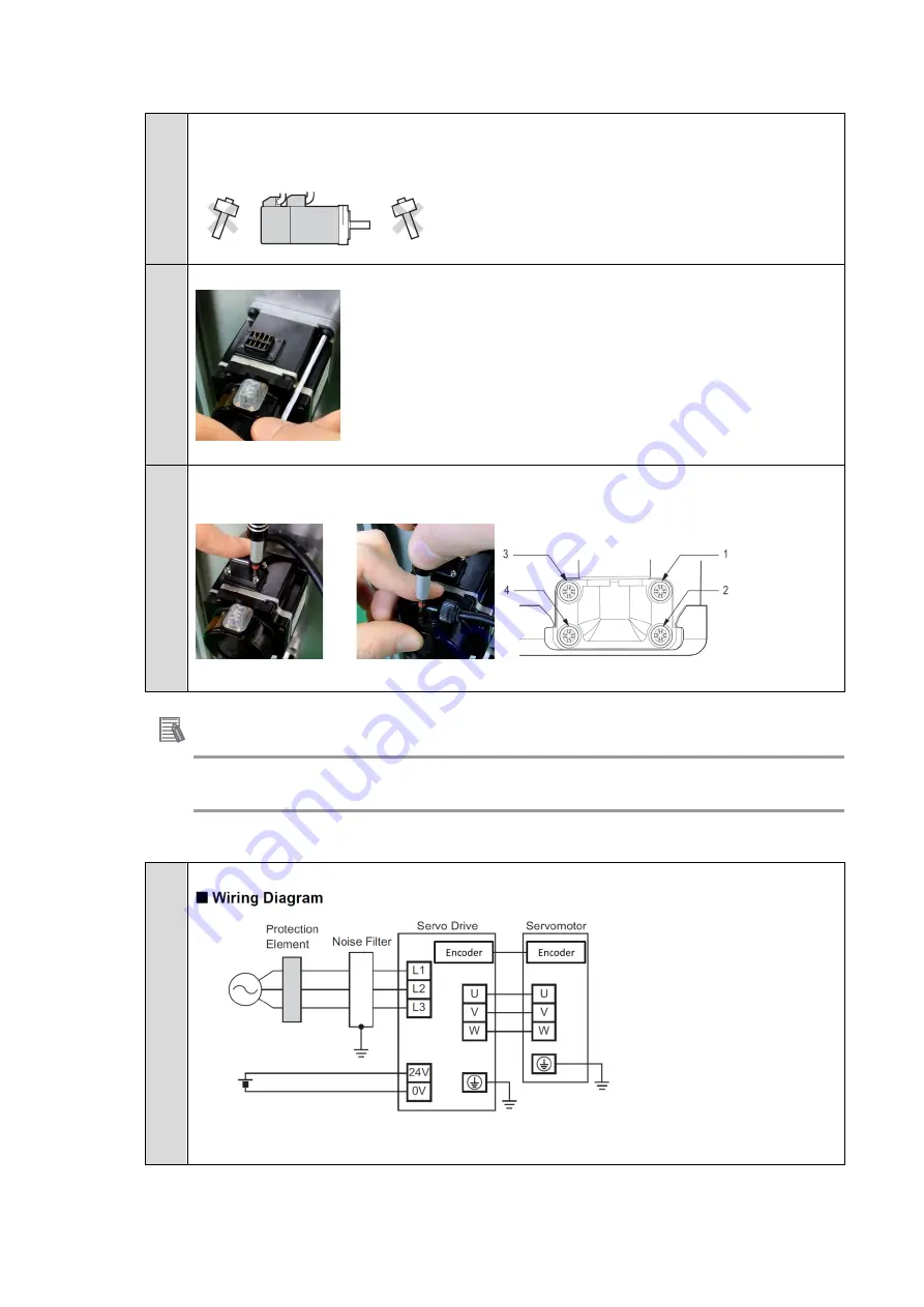
■ Motor installation

 (step 2, 3 order depends on your mechanical implementation)


1. 

Please handle the motor carefully & 

do not apply heavy impacts or loads during 

transport, installation, or removal of the motor. 


2. 

Please fixe and connect the motor to the mechanical system 


Note: At first, please check motor operation without any load.


3. 

Please attached the power and encoder cable   

Here is an example with 200W motor 


Please tight screws in several times in this order :1>4>3>2 


Additional Information 

For further details about coupling method, please refer to 1S-series AC Servomotors and Servo Drives 

User’s Manual (with Built-in EtherCAT Communications) (Cat. No. I586) 


■ Wiring 

1. 

Overview   


For further details please refer to section 4-2 wiring of 1S AC servo drive user’s manual


(Cat. No. I586)


Summary of Contents for R88D-1SNx-ECT Series

Page 1: ...Servo System 1S series Startup Guide R88M 1L 1M AC Servomotors R88D 1SN ECT AC Servo Drives I823 E1 01...

Page 2: ...ith respect to the use of the information contained herein Moreover because OMRON is constantly striving to improve its high quality products the information contained in this manual is subject to cha...

Page 3: ...and precautions for correct use Intended Audience This Guide is intended for the following personnel Personnel in charge of introducing FA systems Personnel in charge of designing FA systems The pers...

Page 4: ...garding the Products unless Omron s analysis confirms that the Products were properly handled stored installed and maintained and not subject to contamination abuse misuse or inappropriate modificatio...

Page 5: ...Omron Company websites catalogs and other materials is provided as a guide for the user in determining suitability and does not constitute a warranty It may represent the result of Omron s test condi...

Page 6: ...to Check the user program for proper execution before you use it for actual operation Trademarks Sysmac and SYSMAC are trademarks or registered trademarks of OMRON Corporation in Japan and other coun...

Page 7: ...nit Software User s Manual Cat No W501 NJ NX series CPU Unit Software User s Manual W501 NJ501 NJ301 Learning how to program and set up an NJ NX series CPU Unit Mainly software information is provided...

Page 8: ...oncepts on managing errors that may be detected in an NJ NX series Controller and information on individual errors Use this manual together with the NJ series CPU Unit Hardware User s Manual Cat No W5...

Page 9: ...story A manual revision code appears as a suffix to the catalog number on the front and back covers of the manual Revision code Date Revised content 01 July 2016 Original production Cat No I823 E1 01...

Page 10: ...ts 11 1 1 Outline 11 1 2 Servo System constructed in this guide 12 1 3 System configuration 13 2 Before You Begin 15 3 Performing setup 16 3 1 Installation Wiring 16 3 2 System configuration with NJ a...

Page 11: ...oller Therefore you can realize a position control system easily with reduced wiring effort With auto tuning adaptive filter notch filter and damping control you can set up a system that provides stab...

Page 12: ...on the system This Guide builds the Servo system in the following steps 1 Installation and wiring 2 System Configuration with NJ and NX safety controller 3 Sysmac Studio project creation and sizing f...

Page 13: ...l Manual name NJ series CPU Unit NJ501 NJ series CPU Unit Hardware User s Manual Cat No W500 NJ series Power Supply NJ P 3001 NX series EtherCAT Coupler NX ECC NX series EtherCAT Coupler Unit User s M...

Page 14: ...14 Automation software Product Number of license Model Sysmac Studio Standard Edition Version 1 16 None DVD only SYSMAC SE200D From 1 license to site license SYSMAC SE...

Page 15: ...copy Warning label 1 sheet General Compliance Information and instructions for EU 1 copy Attached connectors Install the Sysmac Studio Standard Edition Refer to the Sysmac Studio Version 1 Operation M...

Page 16: ...wing When installing side by side S2 can be reduced to 0mm under some conditions temperature inside cabinet should be lower than 45 and install a fan for air circulation to prevent uneven temperatures...

Page 17: ...17 2 Approach the drive from top to down 3 Tight the upper part 4 Tight the down part...

Page 18: ...check motor operation without any load 3 Please attached the power and encoder cable Here is an example with 200W motor Please tight screws in several times in this order 1 4 3 2 Additional Informati...

Page 19: ...with the spring opener Please refer to the corresponding connector depending on your drive and power supply CNA for 100V 200V up to 1kW CND for 200V 1 5kW 3kW 400V 0 6kW 3kW 4 Please wire the AC power...

Page 20: ...and Motor 9 Please fixe the FG wire from the motor cable to the drive Or In case of using the shield clamp please attach the cable to the clamp in order to connect the shielded section 10 Please plug...

Page 21: ...I 0 Safety Wiring 1 By default STO function is inhibited and bypassed with jumpers 2 In case of using STO by hardwire Please make the proper wiring between the safety controller and the drive Servo Dr...

Page 22: ...ardwire for multiple servo drives Please make the proper wiring between the safety controller and drives Note When G9SP series safety controller is used you can connect up to four 1S series Servo Driv...

Page 23: ...r wiring Here is an example of latch input 1 Servo Drive connector view Additional Information For further details about wiring method please refer to 1S series AC Servomotors and Servo Drives User s...

Page 24: ...ase of using NX safety please configure the node address of the NX coupler to 2 Note You can configure the node address depending on your application 3 Please connect EtherCAT cables to devices CN10 E...

Page 25: ...Please select your sizing tool results Note 1 Please refer to the motor sizing tool startup guide for learning how to create the sizing result I820 E1 01 Note 2 If you do not use the sizing file impo...

Page 26: ...meters were updated 6 Axis setting were created and updated If you do not use NX Safety please jump to step 10 7 Add a terminal coupler in EtherCAT editor Double click on Ethercat Drag and drop the te...

Page 27: ...27 8 Add NX Safety unit Double click on NX Coupler Drag and drop NX safety controller 9 Add NX safety I O units Drag and drop Safety I O 10 Please turn on the power supply of all devices...

Page 28: ...etup the method of connection Enter the IP address and test the connection Push connect button 12 Send Program to NJ Push synchronize button Uncheck the below box in order to send drive parameters and...

Page 29: ...tion control MC function module of Sysmac Controller recommended settings should be used Related inputs IN2 POT IN3 NOT IN4 DEC IN7 EXT1 IN8 EXT2 Absolute encoder usage Use as absolute encoder but ign...

Page 30: ...d for resetting the multi turn data or when replacing a motor in actual machine Reset multi turn data Please push clear system This setting required the drive to be restarted Sysmac Studio can do it b...

Page 31: ...alidate the motor operation Apply the test run configuration activate the Servo ON and initiate the movement Note In case of Error 87 00 ESTP input please check your wiring connection or disable the e...

Page 32: ...ith test run By default ESTOP Input is activated please deactivated if necessary as following When ESTP is activated Error 87 00 is present on the drive 9 If necessary Adjust Output settings transfer...

Page 33: ...33 3 5 Easy tuning for gain adjustment Easy tuning Use the following procedure to perform adjustment At first it is recommended to perform easy tuning...

Page 34: ...34 1 Please right click to the drive and select setup and tuning 2 Please select Easy tuning 3 Please select simple mode and click next 4 Please adjust the motion profile...

Page 35: ...cify the position deviation to determine that the positioning is completed If it detects a vibration above the vibration detection level during tuning an adjustment failure will occur If you select th...

Page 36: ...36 7 Please click the record button the motor will move and data will be traced and auto scaled Click next 8 Confirm new gain parameters and save to EEPROM Click Finish...

Page 37: ...TO 1 Please double click on Ethercat 2 Please select the drive and Edit PDO map settings of the drive 3 Select safety input and output 273th It is necessary for setting the information in the safety t...

Page 38: ...38 6 Add the Emergency stop button 7 Add the Reset button 8 Edit I O Map variables...

Page 39: ...39 9 Create safety program 10 Transfer to the controller Please select the controller area Connect to the controller Synchronize with the controller Transfer to the controller...

Page 40: ...load the safety application Please select the new safety CPU Switch to program mode Activate and run the debug mode then Click on safety validation The safety application is now ready to run Please cl...

Page 41: ...he FSoE communication is now established FS LED is green and fixed ON STO is activated when Emergency stop button is pushed STO is released when Emergency stop button was released and RESET button act...

Page 42: ...from the Toolbox to the master on the EtherCAT Tab Page The Servo Drive is added under the master with a node address of 1 Additional Information If the physical EtherCAT network configuration is alr...

Page 43: ...ameters 1 Right click MC_Axis000 axis 0 in the Multiview Explorer and select Edit from the menu Axis 0 is added to the Multiview Explorer The axis is added as MC_Axis000 2 Right click MC_Axis000 axis...

Page 44: ...n node 1 and the drive to the input device for axis 0 5 Set the parameters on the Axis Parameter Settings Tab Page The following figure shows the axis parameters for the unit conversion settings Unit...

Page 45: ...45 6 Operation settings Maximum Velocity 18 000 degree s Maximum Jog Velocity 360 degree s 7 Position count settings Count mode Rotary mode Modulo max 360 Modulo min 0...

Page 46: ...t click to the drive and select test run 2 Please click step tab adjust motion profile and apply 3 Activate the servo ON 4 Please right click to the data trace settings and add a new trace 5 Chose cyc...

Page 47: ...er condition 8 Push record button Sysmac Studio is now waiting for the trigger 9 Place the Test run and Data trace windows side by side with docking window feature Push start in test run data traces w...

Page 48: ...ng Manual tuning guide 1 Please right click to the drive and select setup and tuning 2 Please select Manual Tuning Manual tuning window is displayed It includes rigidity settings gain parameters and d...

Page 49: ...tings and add a new trace 4 Chose cyclic mode 5 Adjust the sampling interval 6 Adjust the trigger condition 7 Disable parameters reading Push record button Sysmac Studio is now waiting for the trigger...

Page 50: ...click Apply 10 Activate the Servo ON and Push Start Be careful the motor will move in the forward and reverse direction 11 The data trace is now triggered and result displayed Each time the motor wil...

Page 51: ...meters to the drive 13 Please repeat step 10 11 and 12 until achieving the desired performance If vibrations appear please reduce the rigidity settings If required It is possible to increase responsiv...

Page 52: ...e explain the way to tune a 1S servo drive and motor with advanced tuning This method of tuning decrease dramatically the number of tests and trial with actual machine 1 Please right click to the driv...

Page 53: ...will move If easy tuning has been performed already please select use present setting Load characteristics have been updated Click Next 4 Frequency response simulation Wizard Step 2 Please start the t...

Page 54: ...54 5 Adjust gain and simulate Please select Maps feature Adjust the gain to a proper value and push refresh simulation Pink curve is the measured value Red curve is the simulated value FROM TO...

Page 55: ...imulate After increasing gains the gain simulation shows a peak near 0dB This peak shows a resonance frequency Activate the cursor to measure the frequency Activate the 1st notch filter to remove this...

Page 56: ...d 8 Time response simulation Wizard step 3 In time response simulation the motion profile can be simulated Please push Simulate Motion Profile The chart is updated and shows The speed command speed de...

Page 57: ...ith the simulation result please transfer parameters to the drive Click Next 10 Check behavior Wizard step 4 Push start trace the motor will move following the previous configuration in Wizard step 3...

Page 58: ...58 11 Results Wizard step 5 Save to EEPROM Finish...

Page 59: ...2016 0616 0616 I823 E1 01 Note Do not use this document to operate the Unit...

Reviews: