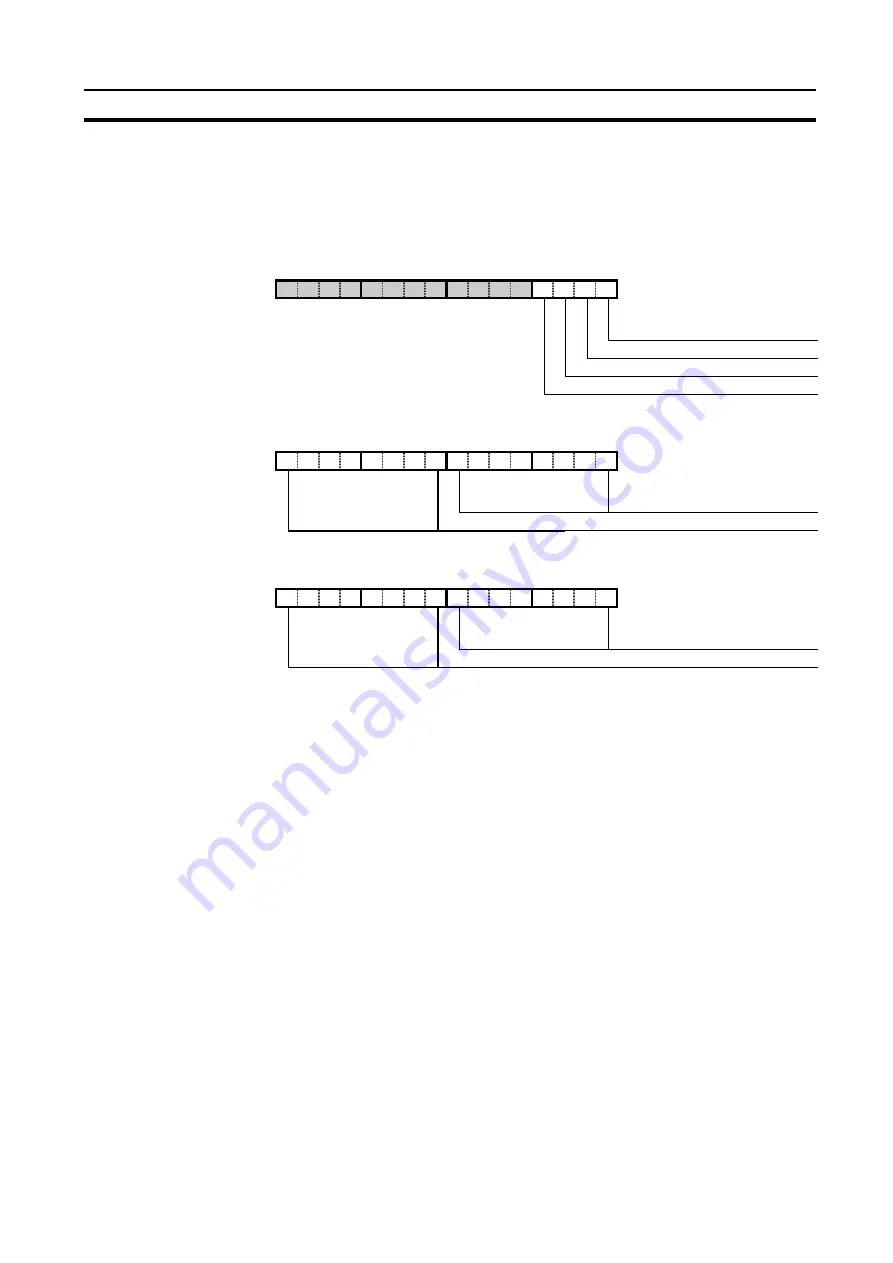
Control and Status area
Section 4-3
61
4-3-1 Control words
The three control words, IR n ~ IR n+2, are shown below.
Any bits of the control words which are not assigned to a specific function,
can freely be used as work bits. These bits will be ignored by the C200HW-
CORT21-V1.
IR n.00
Enable CANopen communication
The main purpose of this bit is enabling / disabling the CANopen
communication, but it also allows the CANopen network to detect
if the host PLC is in abnormal operation.
This bit in the PLC memory needs to be set (in the PLC program
or forced by the user) to enable the CANopen communication. In
case of a fatal PLC error, IR n.00 will revert to 0 and the Unit will
transmit an emergency message to notify the other nodes on the
CANopen network. After transmission of this message, the
C200HW-CORT21-V1 will refrain from CANopen communication
until the bit is set to ON again.
Switching of IR n.00 does not have any effect on the contents of
the object dictionary.
0: CANopen communication is disabled.
The CANopen data exchange between PLC and CAN-bus is
stopped. On a falling edge, the C200HW-CORT21-V1 will first
send out an emergency telegram before disabling the
communication. The status bits IR n+3.01 and IR n+3.00 will
become 0 and the 7-segment display will indicate FFh. In this
mode it is not possible to access the object dictionary, but it is
still possible to transmit / receive user defined CAN messages
(see section 5).
15 14 13 12 11 10 9
8
7
6
5
4
3
2
1
0
IR n
Enable CANopen communication
Start all nodes
Stop all nodes
Start Bus Off recovery
15 14 13 12 11 10 9
8
7
6
5
4
3
2
1
0
IR n+1
Application Object 2000h, 01h
Application Object 2000h, 02h
15 14 13 12 11 10 9
8
7
6
5
4
3
2
1
0
IR n+2
Application Object 2000h, 03h
Application Object 2000h, 04h
Summary of Contents for C200HW-CORT21-V1
Page 2: ...C200HW CORT21 V1 CANopen Slave Unit OPERATION MANUAL OMRON Cat No W904 E2 2 ...
Page 3: ......
Page 4: ......
Page 5: ......
Page 6: ...C200HW CORT21 V1 CANopen Slave Unit Operation Manual Produced June 2001 ...
Page 7: ...iv ...
Page 9: ...vi ...
Page 13: ...x ...
Page 47: ...Performance Section 2 3 30 ...
Page 85: ...Control and Status area Section 4 3 68 ...
Page 113: ...Flow diagrams Section 6 6 96 ...
Page 123: ...Maintenance Section 7 3 106 ...
Page 133: ...116 ...
Page 135: ...118 ...
Page 139: ...122 ...
Page 141: ......


