


LVS-7000 Operations Manual Version 5.6.X
LVS-7000 Operations Manual Version 5.6.X
Page 16 of 187
3.
Click
the
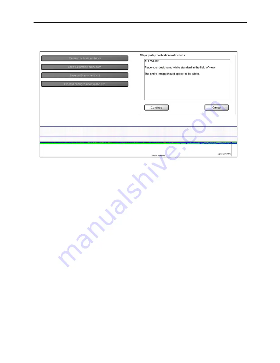
Start calibration procedure
button. The following screen appears:
4.
Place your designated white standard (such as the white porcelain plate, white portion on the calibration
card,
etc.) in the field of view. The entire image should appear white.
Step-by-step calibration instructions are also listed on the right side of the screen.
5.
Observe the colored lines at the bottom of the screen, which represent the scan reflectance profile (SRP) on
the
white background.
The red line represents the current reflectance values across the white background. This represents your
current lighting settings.
The green bar represents the threshold values defined in the Lvs7000.ini file. This is the target area.
The blue line represents the optimal reflectance profile and is configured by an
Omron Microscan
technician.
The red line must fit within the green bar or you will not be allowed to continue with calibration. Ideally, the
red line should overlay the blue line, but the red line must fit within the green bar. If the red line does not fit
within the green bar, your camera may not be pointed at the brightest spot on the designated white
standard. Or, your light may have moved away from the camera’s field of view. Consult
Omron Microscan
technical support if the camera needs adjusting. DO NOT ATTEMPT TO ADJUST THE CAMERA WITHOUT
ASSISTANCE FROM
OMRON
MICROSCAN TECHNICAL SUPPORT.
+1-800-762-1149


