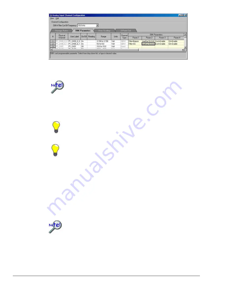
Analog Input Channel Configuration Window
7.
From the
Analog Input Channel Configuration window
, select the
DBK Parameters
tab to view the
specific settings for each DBK channel.
Some DBKs have settings that are physically set on the hardware via jumpers or
switches. In these cases, the designated parameter settings in LogView must agree
with those on the hardware. Setting one does not automatically set the other; in
other words, you must make configuration settings in both software and hardware,
when applicable. For information regarding DBK hardware configuration, refer to
the specific DBK sections, as applicable.
8.
Ensure that the DBK parameters are correctly set at this time. If necessary, refer to the applicable
DBK section for an explanation of the parameters; for example, DBK4 programmable filter values.
You can resize the
Analog Input Channel Configuration window
by dragging its right
edge further to the right. This allows you to see up to four parameters for each channel.
When possible, use User Label names that closely resemble the Physical Channel
names. This practice makes channel identification easier to remember and helps
avoid confusion.
Example:
If Physical Channel P1_CH01 was being used for an alarm, then Alarm-P101
would be a logical User Label.
A note regarding the Range column
:
All LogBook channels and many DBK channels have a programmable gain amplifier (PGA) that
provides multiple ranges. Adjusting the range allows you to zoom in or out on your signal for
maximum signal resolution for the range needed. If the
Units
and/or
Scale
(from the User Scaling
tab) are changed, the available ranges are presented in terms of the new units. For example, if a user
scaling of ×20 is applied to a channel to convert volts to PSI (pounds per square inch), the available
range choices for that LogBook channel would be ±200 PSI, ±100 PSI, ±50 PSI, 0-400 PSI, 0-200
PSI, etc.
Some DBKs have hardware switches and jumpers for configuration. When using
such DBKs, corresponding parameters may need to be set in the LogBook Hardware
Configuration window.
4-6 DBK Setup in LogView
987693
DBK Option Cards and Modules User’s Manual
Summary of Contents for OMB-DBK-34A
Page 6: ...ii...
Page 10: ...viii 917594 DBK Option Cards Modules User s Manual This page is intentionally blank...
Page 32: ...pg 22 DBK Basics 967794 Daq Systems...
Page 60: ...2 10 System Connections Pinouts 877095 DBK Option Cards and Modules...
Page 84: ...5 8 Troubleshooting Tips 967094 DBK Option Cards and Modules...
Page 94: ...DBK200 Series Boards DBK200 DBK201 DD 10 949794 Dimensional Drawings...
Page 96: ...DBK205 DBK205 DD 12 949794 Dimensional Drawings...
Page 97: ...DBK206 Dimensional Drawings 949794 DD 13...
Page 99: ...DBK208 Dimensional Drawings 949794 DD 15...
Page 100: ...DBK209 DD 16 949794 Dimensional Drawings...
Page 101: ...Dimensions for Miscellaneous Components DIN 1 Dimensional Drawings 949794 DD 17...
Page 102: ...DIN 2 DD 18 949794 Dimensional Drawings...
Page 105: ...DBK Cards Modules Part 1 of 2...
Page 106: ...DBK Cards Modules...
Page 108: ...DBK Cards Modules...
Page 148: ...DBK7 pg 14 879895 DBK Option Cards and Modules...
Page 168: ...DBK15 pg 6 889094 DBK Option Cards and Modules...
Page 182: ...DBK16 pg 14 879895 DBK Option Cards and Modules...
Page 200: ...DBK16 pg 32 879895 DBK Option Cards and Modules...
Page 206: ...DBK17 pg 6 879895 DBK Option Cards and Modules...
Page 218: ...DBK20 and DBK21 pg 6 879795 DBK Option Cards and Modules...
Page 232: ...DBK24 pg 8 879795 DBK Option Cards and Modules...


