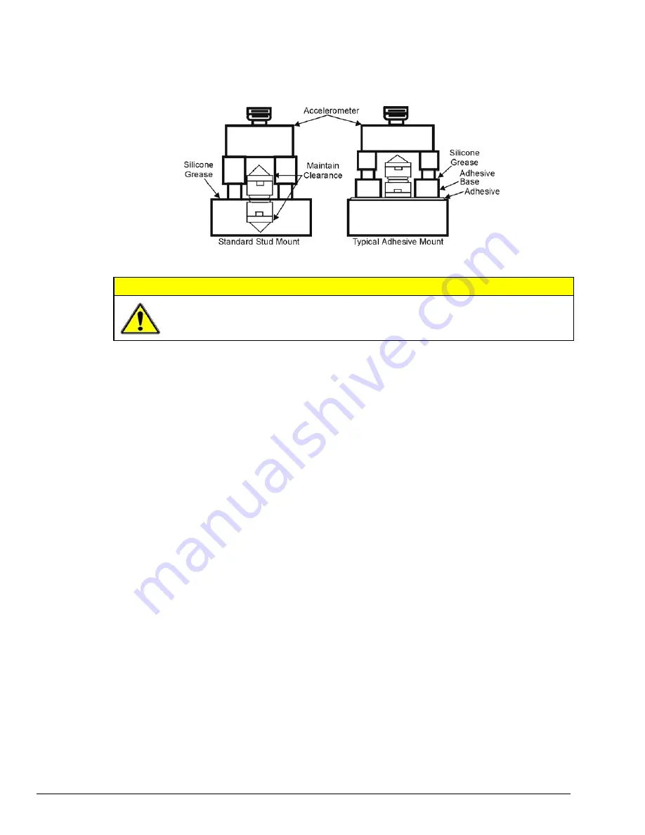
Removal of Adhesive Accelerometers
Many accelerometers and adhesive adapters have been damaged by improper removal. A safe removal
method is to torque the accelerometer or its adapter with a wrench using the flats provided. Adhesives are
generally weakest in the shear mode and will yield under steady torque.
Accelerometer Mounting
CAUTION
Never strike an accelerometer to remove it. The trauma will likely damage the
accelerometer and affect calibration.
Magnetic Mounting Adapters
Magnetic mounting adapters can attach accelerometers to ferromagnetic surfaces such as machinery and
structures where the sensor is to be moved quickly from place to place. The accelerometer is attached to
the magnet (usually by stud mount) and the assembly is then applied to the surface.
In general, use magnetic adapters with caution and never beyond 1 kHz. Expect response degradation in
proportion to accelerometer mass. To ensure the best accuracy from the magnetic mount:
1.
If possible, attach the magnet to bare metal. Paint will lessen the holding force of the magnet and can
affect response.
2.
Clean mounting area to remove oil, grease and foreign matter, which could reduce the contact for a
strong magnetic bond.
3.
Select a flat area to achieve maximum surface contact.
4.
Attach the magnet to the test surface CAREFULLY. Remember that the pull of the magnet rises
sharply just before contact with the ferromagnetic surface. This force could pull the assembly from
your hand resulting in a severe metal-to-metal shock. This could over-range the accelerometer beyond
its maximum shock limit and damage it.
5.
If possible, calibrate the magnetic/accelerometer assembly.
Electrical Grounding
Case-Grounded Design
In case-grounded designs, the common lead on the impedance-matching circuit is tied to the accelerometer
case. The accelerometer base/stud assembly forms the signal common and electrically connects to the shell
of the output connector. Case-grounded accelerometers are connected electrically to any conductive
surface on which they are mounted. When using these units, take care to avoid errors due to ground noise.
Isolated-Base Design
To prevent ground-noise error, many accelerometers have a base-isolated design. The outer case/base of
the accelerometer is isolated electrically off ground by means of an isolation stud insert. The proprietary
material used to form the isolation provides strength and stiffness to preserve high-frequency performance.
DBK4, pg. 14
958293
DBK Option Cards and Modules
Summary of Contents for OMB-DBK-34A
Page 6: ...ii...
Page 10: ...viii 917594 DBK Option Cards Modules User s Manual This page is intentionally blank...
Page 32: ...pg 22 DBK Basics 967794 Daq Systems...
Page 60: ...2 10 System Connections Pinouts 877095 DBK Option Cards and Modules...
Page 84: ...5 8 Troubleshooting Tips 967094 DBK Option Cards and Modules...
Page 94: ...DBK200 Series Boards DBK200 DBK201 DD 10 949794 Dimensional Drawings...
Page 96: ...DBK205 DBK205 DD 12 949794 Dimensional Drawings...
Page 97: ...DBK206 Dimensional Drawings 949794 DD 13...
Page 99: ...DBK208 Dimensional Drawings 949794 DD 15...
Page 100: ...DBK209 DD 16 949794 Dimensional Drawings...
Page 101: ...Dimensions for Miscellaneous Components DIN 1 Dimensional Drawings 949794 DD 17...
Page 102: ...DIN 2 DD 18 949794 Dimensional Drawings...
Page 105: ...DBK Cards Modules Part 1 of 2...
Page 106: ...DBK Cards Modules...
Page 108: ...DBK Cards Modules...
Page 148: ...DBK7 pg 14 879895 DBK Option Cards and Modules...
Page 168: ...DBK15 pg 6 889094 DBK Option Cards and Modules...
Page 182: ...DBK16 pg 14 879895 DBK Option Cards and Modules...
Page 200: ...DBK16 pg 32 879895 DBK Option Cards and Modules...
Page 206: ...DBK17 pg 6 879895 DBK Option Cards and Modules...
Page 218: ...DBK20 and DBK21 pg 6 879795 DBK Option Cards and Modules...
Page 232: ...DBK24 pg 8 879795 DBK Option Cards and Modules...


