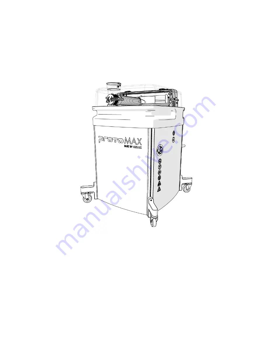
background image

ProtoMAX®


Operation Guide


Lockout/Tagout


Implement standard practices and procedures to shut down equipment, isolate it 
from its energy source(s), and prevent the release of potentially hazardous energy 
while maintenance and servicing activities are


being performed.


Equipment Grounding Requirements
 

Summary of Contents for ProtoMax

Page 1: ...nt standard practices and procedures to shut down equipment isolate it from its energy source s and prevent the release of potentially hazardous energy while maintenance and servicing activities are b...

Page 2: ...a qualified electrician Connecting the EGC improperly can result in electric shock Contact a qualified electrician or service personnel if you do not understand the grounding instructions or if in dou...

Page 3: ...d Mexico OMAX does not supply a suitably rated industrial grade plug Contact a qualified electrician or service personnel for installation of a suitably rated industrial grade plug in accordance with...

Page 4: ...ion pump pressure is monitored to prevent an overpressure condition If the pump exceeds the factory set maximum pressure limit the safety relief valve activates and shuts down the pump unit Electrical...

Page 5: ...te injury NOTICE Used to address practices not related to physical injury property damage only NOTE Used to provide supplementary information emphasize a point or give a tip for easier operation Requi...

Page 6: ...is a precision machining tool that operates under software control using high pressure water and garnet abrasive to cut complex parts out of most materials including metal plastic glass ceramics stone...

Page 7: ...mbly 2 High pressure pump Table Assembly The ProtoMAX table assembly is comprised of the cutting stage garnet abrasive delivery system catcher tank electrical control enclosure water filter and operat...

Page 8: ...ff the pump when the lid is opened Always use the Pause button in the software to pause the system before opening the lid This allows the operator to safely inspect the work and adjust materials as ne...

Page 9: ...coordinate at the lower left corner of the cutting envelope Figure 212 1 X axis 2 Y axis Slat Bed The cutting stage has a removable slat bed assembly to support cutting materials The slat bed assembly...

Page 10: ...from the catcher tank during cutting operations The drain has a flexible tube to adjust the water level as needed and allows cutting underwater The tank overflow allows excess water to exit through t...

Page 11: ...ON position 2 Power selector 3 Power OFF position Garnet Abrasive Delivery System The garnet abrasive delivery system consists of the high pressure nozzle garnet abrasive feed system hopper and feed t...

Page 12: ...urposes only NOTE Always use garnet abrasive purchased from OMAX This high quality abrasive is more consistent in particle size and contains less dust Inconsistency in particle size makes it difficult...

Page 13: ...ube retainer 2 Inlet body weep hole 5 Nozzle body assembly 8 Mixing chamber 3 Nozzle filter 6 Mixing tube 9 Orifice assembly High pressure Pump The high pressure pump provides approximately 30 000 pou...

Page 14: ...ebris from incoming water that can clog and damage the high pressure components The water filter is mounted on the side of the table assembly The outlet water pressure is monitored by the pressure gau...

Page 15: ...tions MAKE software controls the ProtoMAX abrasive waterjet system by sending precise motor control commands to move the nozzle along a part s cutting path while controlling the high pressure water Th...

Page 16: ...YOUT is to convert the drawing file to a machine tool path file ORD OMX that tells the machine how to cut the part MAKE 6 Start up the machine After the drawing file is prepared and converted to a mac...

Page 17: ...le test without abrasive Fill the hopper with garnet abrasive Conduct a nozzle test with abrasive Verify the garnet abrasive is flowing from the hopper to the nozzle Inspect the visible high pressure...

Page 18: ...gnized by the laptop before opening the MAKE program 2 Connect the ProtoMAX USB cable 1 to the laptop Figure 223 3 Turn ON the main power 2 and verify the light 1 is on Figure 224 4 Turn ON the incomi...

Page 19: ...wer switch is turned OFF and then turned back ON during power outages or the main power cord is disconnected Figure 226 8 Conduct a nozzle test without abrasive a Open and secure the lid CAUTION Use c...

Page 20: ...from the nozzle and place it over the top of the Y axis 1 Figure 228 c Verify the mixing tube is properly seated and secured in the nozzle body Figure 229 d Place the nozzle splash guard 1 on the mixi...

Page 21: ...1 in of the surface of the water NOTICE Always hold the nozzle when loosening the hand knob Do not let the nozzle fall and strike the cutting deck slats or material to avoid damage to the nozzle and o...

Page 22: ...9 Fill the hopper with garnet abrasive a Remove the hopper lid Figure 235 b Pour the garnet abrasive through the garnet abrasive screen into the hopper NOTE Gently tap the hopper side to evenly settle...

Page 23: ...ct one end of the garnet abrasive feed tube to the garnet abrasive feed block 1 and connect the other end to the nozzle 2 CAUTION Bacteria in the tank water can build up A minor break in the skin can...

Page 24: ...the nozzle when loosening the hand knob Do not let the nozzle fall and strike the cutting deck slat or material to avoid damage to the nozzle and or nozzle components f Click Test 1 Figure 240 g In T...

Page 25: ...ive is flowing then click Close when the test is complete Figure 243 NOTE The garnet abrasive flow is fast and hard to see The sound increases indicating garnet abrasive is flowing Figure 243 12 Inspe...

Page 26: ...from the side of the table when closing the lid Never let the lid free fall Figure 246 CAUTION Bacteria in the tank water can build up A minor break in the skin can introduce harmful bacteria into a w...

Page 27: ...nozzle at the path start NOTICE To extend the life of the catcher tank cut towards the center of the tank Continuous cutting at the outer edges of the cutting envelop may allow the jet stream to wear...

Page 28: ...al type and thickness for the machine tool path for the part Figure 250 b Click Go home 1 to move the nozzle to the Path Start Home position if needed Figure 251 c Click Begin Machining to display the...

Page 29: ...ial problems are seen during the dry run process to stop nozzle movement Figure 255 g When the dry run is finished click the Close button to close the Path Control dialog Figure 256 19 Click Go Home i...

Page 30: ...ream to wear through the sides of the catcher tank Figure 257 NOTE Cut parts under water when possible Cutting under water lowers the noise level and reduces the mist and splash created by the water a...

Page 31: ...uired sequence Detailed instructions are located in Shutdown the ProtoMAX Position the nozzle for shutdown Remove the abrasive feed tube from the nozzle Run test nozzle to clear the nozzle Close MAKE...

Page 32: ...all Figure 261 b Remove the garnet abrasive tube 1 from the nozzle and place it over the Y axis Figure 262 c Close the lid CAUTION Use care when opening or closing the lid to avoid injury Keep hand fi...

Page 33: ...Figure 263 e Click Test 1 Figure 264 f In Test Operations select Test Cutting Head Pump Jet and Abrasive and click Next Figure 265 g Click Start Test Figure 266...

Page 34: ...r surfaces of the machine Water may enter the electrical control cabinet and damage internal components a Remove any cutting debris from the cutting stage b Remove any cutting debris from the axes bel...

Page 35: ...able base for securing parts for cutting and assists in maximizing material use when cutting It can be used to precisely locate features on existing parts or as a convenient surface to secure material...

Page 36: ...used the nozzle to clog such as wet garnet a blocked orifice a blocked mixing tube or other before continuing operation 1 Remove the garnet abrasive feed tube from the nozzle assembly 2 and the garnet...

Page 37: ...ly from the hopper support plate Figure 275 8 Completely empty and wipe out the hopper NOTE Make sure the hopper container is completely dry prior to filling with dry garnet abrasive Do not reuse garn...

Page 38: ...light is visible through the bore If light is visible 12 Re install the mixing tube 1 into the nozzle body Figure 277 If light is not visible 13 Turn the mixing tube 1 upside down and insert it back...

Page 39: ...ury Keep hand fingers or body part away from the side of the table when closing the lid Never let the lid free fall 17 Open the Test dialog box and run a nozzle test to clear the mixing tube 18 Remove...

Page 40: ...eave fibers and clog the nozzle 22 Apply a light coat of Blue Goop to the second and third threads 1 of the inlet body and then spread the lubricant evenly around the inlet body threads NOTE Use care...

Page 41: ...threads Figure 284 25 Wipe the excess Blue Goop from the end of the nozzle body 1 Figure 285 Once the nozzle is completely clean NOTICE Always orient the orifice assembly so the brass 1 is visible fr...

Page 42: ...install the nozzle assembly on the nozzle inlet body Figure 288 28 Close the Path Control window 29 Re install the hopper and its components abrasive feed block feed tube ground strap and hopper splas...

Page 43: ...ening or closing the lid to avoid injury Keep hand fingers or body part away from the side of the table when closing the lid Never let the lid free fall To continue cutting the part using MAKE 35 Clic...

Page 44: ...ce to reset the pump This test should be done before operating the ProtoMAX for the first time after changing the nozzle orifice repairing or replacing the pump repairing any high pressure plumbing le...

Page 45: ......

Reviews: