background image

EPANA 6 kW

DE

Bedienungsanleitung  

für den Benutzer


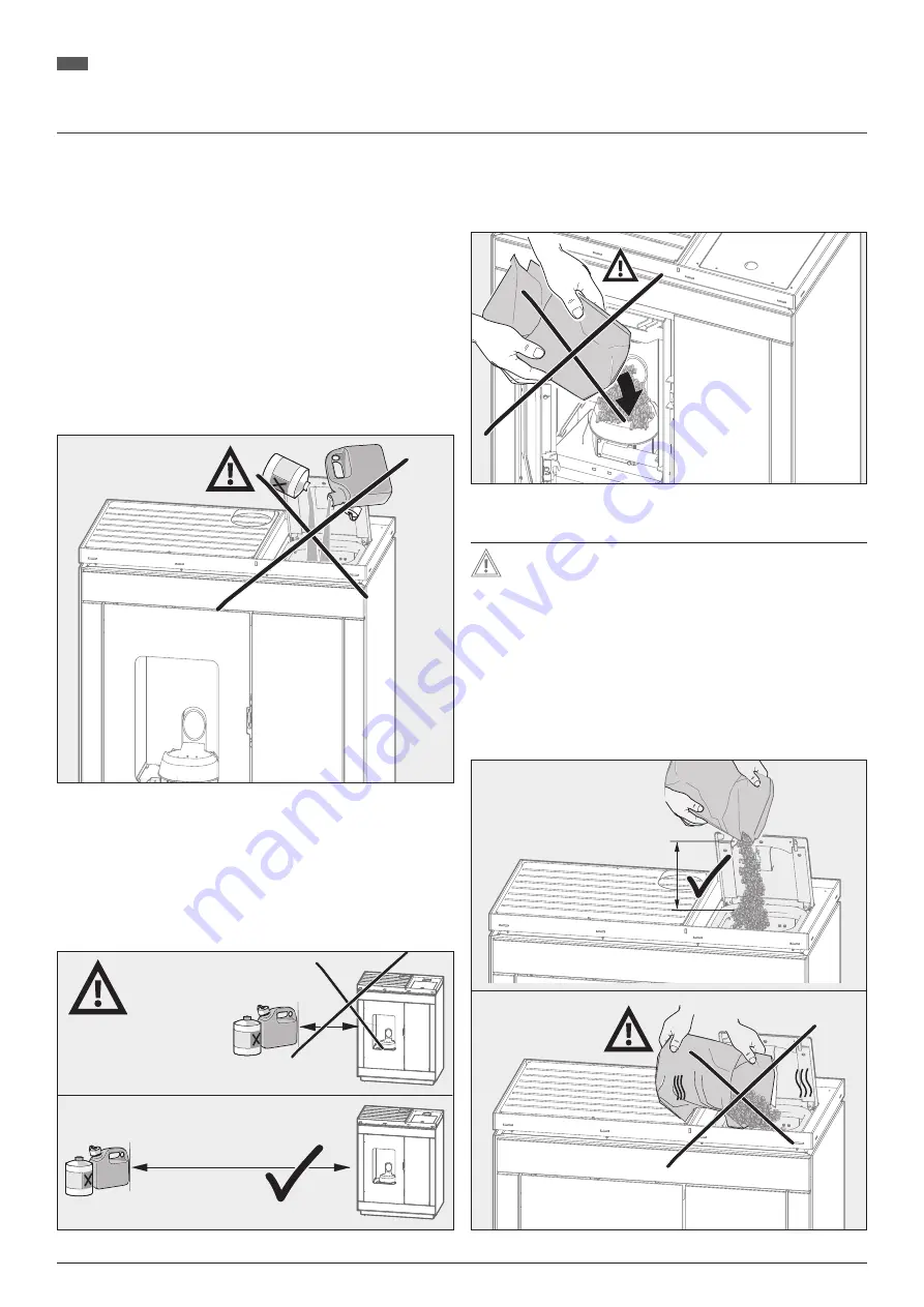
Lassen Sie keine anderen Stoffe außer die oben genann-
ten Pellets in die Brennermulde gelangen! Die Verbrennung 
von anderen brennbaren Materialien oder von Abfällen 
verursacht Schäden am Pellet-kaminofen und führt zum 
Erlöschen der Garantie!


Verwenden Sie niemals brennbare Flüssigkeiten wie Benzin, 
benzinartige Lampenöle, Petroleum, Grillkohleanzünder, 
oder ähnliche Flüssigkeiten zum Entfachen oder „Wieder-
entzünden“ eines Feuers! Achten Sie zudem auf einen aus-
reichenden Abstand von derartigen Flüssigkeiten zum 
Pellet-kaminofen während des Betriebes!

Abb. 3.5   Niemals brennbare Flüssigkeiten verwenden


Pellets dürfen keinesfalls manuell in die Brennermulde ein-
gelegt werden, mit folgender Ausnahme: nach leer gelau-
fenem Tank muss eine Handvoll Pellets in die Brennermulde 
Richtung Zündelement gefüllt werden. Ansonsten wird in 
der Startphase innerhalb des Befüllzeitraums lediglich der 
Pelletschacht gefüllt und nur unzureichende Pellets fallen in 
die Brennermulde. 

Abb. 3.6   Auf ausreichend Abstand zu brennbaren Flüssigkeiten achten

Abb. 3.7   Pellets nicht manuell in die Brennermulde füllen, außer nach leer 

gelaufenem Tank 

  Achtung! Beschädigung der Lackoberfläche!

Der Pellet-kaminofen ist mit einem hochwertigen temperatur-
beständigen Lack beschichtet, der seine endgültige Festigkeit 
erst nach dem ersten Aufheizen erreicht. 


Stellen Sie deshalb nichts auf den Pellet-kaminofen und be-
rühren Sie nicht die Oberflächen, da sonst die Lackierung 
beschädigt werden könnte!


Legen Sie den Pelletsack keinesfalls auf die Abdeckhaube!


Beachten Sie, dass Verpackung die heißen Oberflächen 
nicht berührt, wenn Sie die Pellets einfüllen, da 
Verpackungsrückstände sich in die Lackoberfläche einbren-
nen können!

Abb. 3.8  Pelletsack beim Einfüllen nicht auf heiße Oberflächen legen

13

Technische Änderungen und Irrtümer vorbehalten  

Summary of Contents for EPANA 6 kW

Page 1: ...hbetrieb Bedienungsanleitung f r den Benutzer DE Pellet fireplace Installation instructions for the specialist company Operating manual for the user EN Po le granul s Instructions de montage pour l en...

Page 2: ...el Rauchgasz ge Cast cover flue gas flues Couvercle en fonte conduits de gaz de combustion 14 Konvektionsluft ffnungen Convection air openings Ouvertures d air de convection 15 Anschlussstutzen Abgasr...

Page 3: ...nd safety information 34 2 Installation instructions 36 3 Operating manual 42 4 Cleaning care and maintenance 57 5 General warranty conditions 59 6 Product information and labelling 61 7 Commissioning...

Page 4: ...hren verstanden haben Kinder d rfen nicht mit dem Pellet Kaminofen spielen Reinigung und Benutzer Wartung d rfen nicht durch Kinder ohne Beaufsichtigung durchgef hrt werden 1 4 Gew hrleistung und Haft...

Page 5: ...lten Sie sich an vorgegebene Mindestabst nde bei der Montage und beim Gebrauch des Pellet Kaminofens Verwenden Sie niemals brennbare Fl ssigkeiten wie Benzin ben zinartige Lampen le Petroleum Grillkoh...

Page 6: ...timmt Folgende Werkzeuge werden f r die Montage des Pellet Kaminofens ben tigt Saubere Schutzhandschuhe Cuttermesser Wasserwaage Abb 2 2 Erforderliches Werkzeug 2 3 Typenschild Abb 2 3 Typenschild 2 4...

Page 7: ...ungsbereich des Pellet Kaminofens d rfen keine Gegenst nde aus brennbaren Stoffen vorhanden sein oder abge stellt werden Der Abstand des Pellet Kaminofens zu brennbaren Materialien oder zu sch tzenden...

Page 8: ...utzen 182 0 C Mindestf rderdruck bei Nennw rmeleistung 5 0 Pa Richten Sie bei zu hohen F rderdr cken 20 Pa eine F rderdruck begrenzung z B Nebenluftvorrichtung im Schornstein ein Setzen Sie bei der Sc...

Page 9: ...n Verbrennungsluftstutzen Option wenn die Verbrennungsluft nicht aus dem Aufstellraum sondern ber eine Leitung raumluftunabh ngig zugef hrt werden soll Bringen Sie am Pellet Kaminofen die Verbrennungs...

Page 10: ...finden oder abgestellt werden siehe Kap 2 6 Pr fen Sie vor dem ersten Heizen ob alle Zubeh rteile aus dem Aschekasten und Feuerraum entfernt wurden ffnen Sie die Feuerraumt r und ziehen Sie den Aschek...

Page 11: ...orderlichen Wartung Fachbetrieb Unterweisen Sie den Benutzer der Anlage insbesondere in die von dem Pellet Kaminofen ausgehenden Gefahren sowie ber die Sicherheitshinweise und Sicherheitsvorkehrungen...

Page 12: ...etbeh lter mit Pellets Verwenden Sie ausschlie lich Pellets nach DIN EN 14961 2 und dem Zertifizierungsprogramm DIN plus oder der Norm M 7135 max 30 mm max 10 DIN EN 14961 2 Zertifizierungsprogramm DI...

Page 13: ...ng Z ndelement gef llt werden Ansonsten wird in der Startphase innerhalb des Bef llzeitraums lediglich der Pelletschacht gef llt und nur unzureichende Pellets fallen in die Brennermulde Abb 3 6 Auf au...

Page 14: ...ist Entnehmen Sie keine hei e Asche und lagern Sie Asche nur in feuersicheren unbrennbaren Beh ltern Warnung Schwere Personen Umwelt und Sachsch den Verwenden Sie den Pellet Kaminofen keinesfalls wen...

Page 15: ...ige verbrennungsbezogene Daten und Einstellungen ab Wird der Pellet Kaminofen wieder mit Spannung versorgt wird er auf den Betriebszustand vor dem Stromausfall geregelt Ist der Pellet Kaminofen l nger...

Page 16: ...gnalfarbe Rot wird nachfolgend als Tiefschwarz zu erkennen sein Schwarze Symbole und Texte Ihres Touch Bedienfeldes sind in Dunkelgrau dargestellt Anzeige HOME Leistungsstufe Bereit Party Ist in C 16...

Page 17: ...eit ist innerhalb der Schaltzeit bei aktiver Schaltzeit Z nden Die Pellets werden automatisch in die Brennermulde eingeworfen und entz ndet Bei der Erstinbetriebnahme dauert das Z nden l nger da sich...

Page 18: ...tellten Raumtemperatur in kleinster Leistungsstufe weiter Dadurch werden Z ndvorg nge vermieden Im Standby Betrieb schaltet sich der Pellet Kaminofen bei Erreichen der eingestellten Raumtemperatur zuz...

Page 19: ...tufe 1 entspricht Teilw rmeleistung Leistungsstufe 5 entspricht Nennw rmeleistung Werkseinstellung 4 Betriebsart Automatik Manuell Automatik Betriebsart Abb 3 21 Touch Bedienfeld Betriebsart Manuell I...

Page 20: ...muss am ersten Tag die Schaltzeit bis 23 59 und am Folgetag ab 0 00 eingegeben werden F r jeden Tagesblock bzw Wochentag k nnen 3 verschiedene Schaltzeitpaare definiert werden Wenn eine Solltemperatur...

Page 21: ...m Betriebszustand Automatik einstellbare Raumtemperatur auf den Maximalwert 40 C eingestellt werden Mit Hilfe dieser Anzeige kann berpr ft werden ob der ex terne Raumthermostat richtig angeschlossen w...

Page 22: ...dung herstellen WLAN Einstellungen Kein WLAN gespeichert 2 APP Parameter eingeben APP Einstellungen Abb 3 32 Touch Bedienfeld WLAN Empfang eingeschaltet 15 41 WLAN 1 Internet Verbindung herstellen WLA...

Page 23: ...Men ffnen Automatik Bereit 08 17 Soll in C 25 Party Abb 3 39 WLAN Einstellungen ffnen 08 17 WLAN Abb 3 40 WLAN aktivieren 15 41 WLAN 1 Internet Verbindung herstellen WLAN Einstellungen Kein WLAN gespe...

Page 24: ...ahme 1oT Version iot 10154786794 103297 olsberg 1 01 02 Abb 3 45 Name ID Pin eingeben und App verbinden 3 9 Bedienung Ambiente Beleuchtung Der EPANA verf gt ber eine Ambiente Beleuchtung LED Button an...

Page 25: ...mmsensor defekt Flammtemperatursensor defekt Flammtemperatursensor nicht angeschlossen Servicetechniker anfordern Raumsensor defekt Raumtemperatursensor defekt Raumtemperatursensor nicht angeschlossen...

Page 26: ...tartet Die gew nschte Temperatur am Raumthermostat erh hen Au erhalb der Schaltzeiten Es sind aktive Schaltzeiten hinterlegt die ak tuelle Uhrzeit ist jedoch au erhalb der aktiven Schaltzeiten In der...

Page 27: ...sdeckel abnehmen Schritt 4 Verschraubungen der beiden Reinigungsklappen l sen Schritt 5 Reinigungsklappen rechts und unten entfernen Schritt 6 Abgasz ge mit Reinigungsb rste s ubern Schritt 7 und durc...

Page 28: ...htpr fung Pr fung des Luftabgassystems L A S auf Dichtigkeit Verschlei Besch digungen 1 x pro Jahr mit Pr fger t 4 2 Wartung und Instandhaltung durch den Fachbetrieb min einmal j hrlich Siehe Wartungs...

Page 29: ...luss an die vorge schriebene Betriebsspannung und bei Betrieb mit der angegebe nen Energieart bzw mit den in der jeweiligen ger tespezifischen Aufstell und Bedienungsanleitung zugelassenen vorgeschrie...

Page 30: ...serer Wahl durch Reparatur oder Lieferung einer mangelfreien Sache innerhalb eines angemessenen Zeitraumes durch uns oder einem von uns erm ch tigten Fachbetrieb Der Sachmangel ist unverz glich sp tes...

Page 31: ...EPANA 6 kW DE Produktinformationen und kennzeichnungen 6 Produktinformationen und kennzeichnungen 6 1 Produktdatenblatt Technische nderungen und Irrt mer vorbehalten 31...

Page 32: ...EPANA 6 kW DE Produktinformationen und kennzeichnungen 6 2 Leistungserkl rung 32 Technische nderungen und Irrt mer vorbehalten...

Page 33: ...W DE Produktinformationen und kennzeichnungen 6 3 Energielabel A A B C D E F G A 2015 1186 6 0 kW ENERGIA ENERGIJA ENERGY ENERGIE ENERGI A A A A A EPANA 43 406 Technische nderungen und Irrt mer vorbeh...

Page 34: ...et fireplace Cleaning and user mainte nance may not be carried out by children without supervision 1 4 Warranty and liability Warranty and liability claims for personal injury and property damage are...

Page 35: ...inimum distances during instal lation and use of the pellet fireplace Never use flammable liquids such as petrol lamp oils si milar to petrol petroleum firelighters or similar liquids to kindle or rei...

Page 36: ...llation The following tools are required for installation of the pellet fire place Clean protective gloves Cutter knife Spirit level Fig 2 2 Necessary tools 2 3 Type plate Fig 2 3 Type plate 2 4 Techn...

Page 37: ...from flammable objects No objects made from flammable material may be present or placed in the radiation range of the pellet fireplace The distance from the pellet fireplace to flammable materials or...

Page 38: ...le 182 0 C Minimum pump pressure at nominal heat output 5 0 Pa If the pump pressures are too high 20 Pa then you should set up pump pressure limitation e g draft regulator in the chimney Set the requi...

Page 39: ...ustion air should be supplied not from the room in which it is installed but rather independently from the room air via a line Attach the 60 mm combustion air line to the rear of the pellet fireplace...

Page 40: ...pan and combustion chamber Open the firebox door and pull out the ash box to the front Remove the protective film from the touch control panel Convection air openings may not be covered The precaution...

Page 41: ...in the safety information and safety precautions Hand the product the system over to the user together with this manual and all other documents Commissioning certificate The proper installation commi...

Page 42: ...only pellets which comply with DIN EN 14961 2 and the DIN plus certification programme or the Austrian standard M 7135 When pouring in the pellets take care to ensure that the sawdust which may be pr...

Page 43: ...lled within the filling period in the start phase and only an insufficient pellets will fall into the bur ner trough Fig 3 5 Never use flammable liquids Fig 3 6 Maintain a sufficient distance from fla...

Page 44: ...is in use and hot Do not remove hot ashes and only store ashes in fireproof non flammable containers Warning Serious personal injury environmental damage and property damage Do not under any circumst...

Page 45: ...e power to the pellet fireplace is restored it is regulated to the operating state before the power failure If the pellet fireplace is without power for more than 14 days then the data and time must b...

Page 46: ...l The signal colour red can be recognised below as deep black Black symbols and text on your touch control panel are shown in dark grey HOME display Manual mode Ready Party Actual C 16 20 17 4 Fig 3 1...

Page 47: ...he set value The current time is within the switching time with switching time active Ignition The pellets are automatically deposited in the burner trough and ignited Ignition takes longer during ini...

Page 48: ...hed off the pellet fireplace continues heating at the lowest output stage once the preset room temperature is reached This means ignition processes are avoided In standby mode the pellet fireplace swi...

Page 49: ...me Output stage 1 corresponds to the partial heat output Output stage 5 corresponds to the nominal heat output Factory setting 4 Automatic operating mode Manual Auto Operation mode Fig 3 21 Touch cont...

Page 50: ...an 24 hours should be defined then a switch off time of 23 59 must be entered for the first day with a switch on time of 0 00 for the following day 3 different switching pairs can be defined for each...

Page 51: ...hen the room temperature which can be set in Automatic mode must be set to the maximum value 40 C This display can be used to check whether the external room ther mostat has been connected correctly a...

Page 52: ...ternet connection WiFi settings No WiFi saved 2 Insert app credentials App settings Fig 3 32 Touch control panel Wi Fi receiver switched on 15 41 WiFi 1 Set internet connection WiFi settings Active Wi...

Page 53: ...20 17 25 Actual C Ready Desired C Fig 3 38 Open menu Auto Ready 08 17 Desired C 25 Party Fig 3 39 Open Wi Fi settings 08 17 WiFi Fig 3 40 Activate Wi Fi 15 41 WiFi 1 Set internet connection WiFi setti...

Page 54: ...ype here Type here Type here Please select Type here Fig 3 45 Enter name ID PIN and connect app 3 9 Ambient lighting operation EPANA has ambient lighting Select the LED button choose the desi red colo...

Page 55: ...n Flame sensor faulty Flame temperature sensor faulty Flame temperature sensor not connected Call a service technician Room sensor faulty Room temperature sensor faulty Room temperature sensor not con...

Page 56: ...lly Increase the desired temperature on the room thermostat Outside the switching times Active switching times are saved and the current time is outside the active switching times In Automatic operati...

Page 57: ...nnections from the cast cover step 3 Remove the cast cover step 4 Loosen the screw connections of the two cleaning flaps step 5 Remove the cleaning flaps on the right and at the bottom step 6 Clean th...

Page 58: ...app Visual inspection for surface damage 1 x per year Visual inspection Testing of the exhaust system for leaks wear damage 1 x per year With testing instrument 4 2 Maintenance and servicing by the s...

Page 59: ...ppliance specific installation and operating manual We provide a two year warranty for the durability of door hinges glass ceramics not breakage of glass and surfaces plat ings e g gold chrome with th...

Page 60: ...l defect must be reported to Olsberg via the responsible specialist company immediately and within two weeks of discov ery at the latest If the material defect is indicated in good time within the war...

Page 61: ...EPANA 6 kW EN 6 Product information and labelling 6 1 Product data sheet We reserve the right to make technical changes 61...

Page 62: ...EPANA 6 kW EN 6 2 Declaration of performance Product information and labelling 62 We reserve the right to make technical changes...

Page 63: ...6 kW EN 6 3 Energylable A A B C D E F G A 2015 1186 6 0 kW ENERGIA ENERGIJA ENERGY ENERGIE ENERGI A A A A A EPANA 43 406 Product information and labelling We reserve the right to make technical chang...

Page 64: ...s jouer avec le po le granul s Le nettoyage et l entretien par l utilisateur ne doivent pas tre effectu s par des enfants sans surveillance 1 4 Garantie et responsabilit Les demandes de garantie et de...

Page 65: ...ez ce qu il y ait une distance suffisante entre le po le granul s y compris le conduit d vacuation d air et les rideaux tapis tissus d ameublement et autres mat riaux combustibles Il est interdit de p...

Page 66: ...saires pour l installation du po le granul s Gants de protection propres Coutau de coupe Niveau bulle Douille hexagonale Allen 3 4 Fig 2 2 Outils n cessaires 2 3 Plaque signal tique Fig 2 3 Plaque sig...

Page 67: ...les Aucun objet en mat riau inflammable ne doit tre pr sent ou pla c dans la zone de rayonnement du po le granul s l arri re la distance entre le po le granul s et les mat riaux in flammables ou les m...

Page 68: ...raccordement 182 0 C Pression de refoulement minimale en pr sence de la puissance calorifique nominale 5 0 Pa Si les pressions de refoulement sont trop lev es 20 Pa instau rez une limitation de la pr...

Page 69: ...on de 60 mm sur le man chon d arriv e d air de combustion en option lorsque l air de combustion ne doit pas venir du lieu d installation mais d une conduite sans tirage Installez la conduite d air de...

Page 70: ...e rayonnement du foyer voir chap 2 6 Avant de chauffer pour la premi re fois v rifiez que tous les ac cessoires ont t retir s du bac cendres et du foyer Ouvrez la porte du foyer et tirez le bac cendre...

Page 71: ...nctionnement l entretien et le nettoyage utilisateur l entretien annuel n cessaire entreprise sp cialis e Instruisez l utilisateur de l quipement notamment sur les dan gers li s au po le granul s ains...

Page 72: ...anul s Utilisez uniquement des gra nul s conformes la norme DIN EN 14961 2 et au programme de certification DIN plus ou la norme cologique M 7135 Lorsque vous proc dez au remplissage des granul s veil...

Page 73: ...age Autrement seul le puits de granul s se remplit lors de la phase de d marrage pendant la p riode de remplissage et seuls granul s tombent dans la cuvette de combustion ce qui est insuffisant Abb 3...

Page 74: ...e chaude et stockez la cendre unique ment dans des r cipients ignifuges et non inflammables Danger Blessures corporelles dommages mat riels et atteintes l environnement graves N utilisez en aucun cas...

Page 75: ...s en lien avec la combustion Si le po le granu l s est nouveau mis sous tension il se remet dans le mode de fonctionnement dans lequel il tait avant la panne lectrique Si le po le granul s n est pas s...

Page 76: ...eur de signalisation rouge est repr sent e par du noir intense Les symboles et textes inscrits en noir sur votre panneau de commande tactile sont repr sent s en gris clair Affichage HOME Mode manuel P...

Page 77: ...nement est activ Allumage Les granul s sont automatiquement introduit dans la cuvette de combustion et enflamm En cas de premi re mise en service l allumage prend plus de temps tant donn que l h lice...

Page 78: ...peut tre activ ou d sactiv Lorsque le mode Veille est d sactiv le po le granul s chauffe un niveau de puissance moins lev une fois la temp rature ambiante pr r gl e atteinte Cela viter d avoir recours...

Page 79: ...issance 1 5 Le niveau de puissance 1 correspond une puissance calorifique partielle Le niveau de puissance 5 correspond la puissance calorifique nominale R glage d usine 4 Mode automatique Manuel Auto...

Page 80: ...24 h doit tre d fini le cr neau doit aller jusqu 23h59 le premier jour et commencer 0h00 le jour suivant 3 paires de cr neaux horaires diff rents peuvent tre d finis pour chaque blocs de jours ou chaq...

Page 81: ...tique doit tre r gl e la valeur maximale 40 C Cet affichage permet de v rifier si le thermostat externe a t cor rectement raccord et s il prend en compte le r glage du po le granul s Lors du r glage d...

Page 82: ...tres d WLAN Pas de WLAN enregistr 2 Param tres de l application Application Fig 3 32 Panneau de commande tactile Acc s au Wi fi activ 15 41 WLAN 1 Param tres d Internet Param tres d WLAN R seau wi fi...

Page 83: ...ique Ready 08 17 D finie C 25 F te Fig 3 39 Ouvrir les param tres Wi fi 08 17 WLAN Fig 3 40 Activer le Wi fi 15 41 WLAN 1 Param tres d Internet Param tres d WLAN Pas de WLAN enregistr 2 Param tres de...

Page 84: ...Entrer un texte Entrer un texte Entrer un texte Please select Fig 3 45 Saisir le nom l identifiant et le PIN et se connecter l application 3 9 Bedienung Ambiente Beleuchtung L EPANA dispose d un clair...

Page 85: ...d un technicien Sonde d ambiance d fectueuse Capteur de temp rature d ambiance d fectueux Capteur de temp rature d ambiance non raccord Solliciter l aide d un technicien Cha ne de s curit interrompue...

Page 86: ...oraires Des cr neaux horaires actifs sont enregistr s l heure actuelle est toutefois en dehors des cr neaux ho raires actifs En outre en mode automatique aucune baisse de la temp rature la nuit n est...

Page 87: ...vis du couvercle en fonte tape 3 Retirer le couvercle en fonte tape 4 D visser les vissages des deux trappes de nettoyage tape 5 Retirer les trappes de nettoyage droite et en bas tape 6 Nettoyer les c...

Page 88: ...visuel des dommages superficiels 1 x par an Contr le visuel Contr le de l tanch it de l usure et de l endommagement du syst me d chappement d air L A S 1 x par an Avec appareil de mesure 4 2 Maintenan...

Page 89: ...pareil est raccord la tension de service sp cifi e et s il est utilis avec le type d nergie sp cifi ou avec les combustibles sp cifi s approu v s dans les instructions d installation et d utilisation...

Page 90: ...uts de production et ou de mat riaux Le d faut sera r par notre discr tion par une r paration ou la livraison d un article sans d faut dans un d lai raisonnable par nous ou par une entreprise sp ciali...

Page 91: ...EPANA 6 kW FR 6 Informations et tiquetage des produits 6 1 Fiche technique po le bois Sous r serve de modifications techniques 91...

Page 92: ...EPANA 6 kW FR Informations et tiquetage des produits 6 2 D claration des prestation 92 Sous r serve de modifications techniques...

Page 93: ...kW FR Informations et tiquetage des produits 6 3 Label nerg tique A A B C D E F G A 2015 1186 6 0 kW ENERGIA ENERGIJA ENERGY ENERGIE ENERGI A A A A A EPANA 43 406 Sous r serve de modifications techni...

Page 94: ...vailable Note the stove ID can be found on the display under app settings Nous prions d envoyer le certificat de mise en service sign la soci t Olsberg La garantie ne peuvent tre fournie que si un cer...

Page 95: ...e Telefon mobil Phone mobile T l phone portable Bemerkungen Notes Remarques Mitarbeiterkennzeichen f r Inbetriebnahme verantwortlich Employee identifier responsible for commissioning Code de l employ...

Page 96: ...ch Ihnen das unterzeichnete Inbetriebnahmezertifikat Dear Sir Madam In order to receive all services pursuant to the warranty in case of damage I send you the signed commissioning certificate Mesdames...

Page 97: ...ortable Bemerkungen Notes Remarques Mitarbeiterkennzeichen f r Inbetriebnahme verantwortlich Employee identifier responsible for commissioning Code de l employ responsable de la mise en service Ger te...

Page 98: ...EPANA 6 kW 98 Technische nderungen vorbehalten We reserve the right to make technical changes Sous r serve de modifications techniques...

Page 99: ...EPANA 6 kW Technische nderungen vorbehalten We reserve the right to make technical changes Sous r serve de modifications techniques 99...

Page 100: ...Olsberg GmbH H ttenstra e 38 59939 Olsberg T 49 2962 805 0 F 49 2962 805 180 kaminofen olsberg com olsberg com 78 4643 4061 08 2023...

Reviews: