29
OLCT 200 User Manual |
29
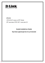
on the HART board and connect the leads from the Hart handheld. They can be
accessed without pulling the nest assembly out of the enclosure and are on the top
right side, just above the next button (See Figure 2.14).
+ -
Connection Points for
Connecting HART Handheld
Figure 2-14: Top View of OLCT 200 showing HART connection terminals
At the controller end, connect the HART handheld directly across the signal and
common wires coming from the HART modem. In applications that utilize WX series
controllers, the terminals are labeled HI and LO with HI being the signal and LO being
common.
Figure 2-15: Example of OLCT 200 HART Wiring
Summary of Contents for OLCT 200
Page 4: ...OLCT 200 User Manual 4...
Page 14: ...OLCT 200 User Manual 14 Figure 2 3a Outline Drawing OLCT 200 Wired Models...
Page 19: ...OLCT 200 User Manual 19 2 6 2 Installation Drawing 11 0100...
Page 32: ...OLCT 200 User Manual 32...
Page 36: ...OLCT 200 User Manual 36...
Page 38: ...OLCT 200 User Manual 38 Figure 4 1 Calibration Gas Input...
Page 61: ...OLCT 200 User Manual 61 Figure 6 5...
Page 62: ...OLCT 200 User Manual 62...
Page 79: ...OLCT 200 User Manual 79...