


40 - 97
Instruction Manual
AC 02/2019-rev.1.1
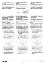
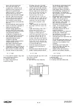
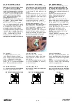
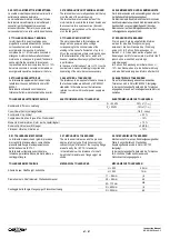
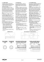
5.0.4 SPAZZOLA SCARICO CORRENTI
Alcuni motori sono provvisti di serie di una
spazzola per
scarico correnti d’albero
La spazzola
ha lo scopo di chiudere il circuito elettrico
esistente tra il rotore e la struttura del motore
consentendo il passaggio delle correnti d’albero
tramite la spazzola e non attraverso i cuscinetti.
La spazzola di scarico correnti d’albero mette in
contatto diretto il rotore con la struttura del
motore creando una via preferenziale per il
passaggio delle correnti di rotore.
Normalmente è posizionata nella parte posteriore
del motore ma in alcuni casi potrebbe essere
installata anche dal lato albero.
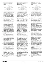
Prevedere un ispezione periodica ogni 8.000 ore
circa di funzionamento e la sostituzione quando
rimangono circa 5mm utili di materiale conduttivo.
Se durante la sostituzione della spazzola il
portaspazzole viense smontato o ruotato, è
necessario riposizionarlo angolarmente facendo
in modo che, senza la spazzola, il braccio mobile
in metallo non venga a contatto direttamente con
l’albero. L’eventuale stridio della spazzola è
facilme
nte eliminabile con l’applicazione di
qualche goccia di lubrificante per contatti elettrici.
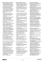
5.0.4 BRUSH FOR SHAFT CURRENTS
Some motors are provided as standard with a
shaft currents brush. Its purpose is to close the
electric circuit existing between the rotor and
the motor structure, allowing the shaft currents
to pass through the brush and not in the
bearings.
The shaft current discharge brush puts the rotor
in direct contact with the motor structure,
creating a preferential way for the passage of
the rotor currents.
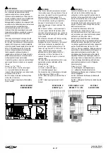
Normally the brush is installed on the rear side
of the motor but in some cases it could be
installed also on the fron side. It is necessary to
establish a periodical check every 8.000
working hours and the brush replacment when
there are 5mm aprox of conductive carbon
brush. If during the brush replacment the brush
holder is disassembled or rotated it is
necessary to reassemble it with correct angular
position so that the movable arm without the
brush do not touches the shaft surface.To avoid
possible noise or screech generated by the
brush it is possible to add some electrical
contact lubricating spray unde the brush.
5.0.4 FEHLERSTROMBÜRSTE
Manche Motoren sind standardmäßig mit einer
Fehlerstrombürste ausgerüstet. Diese hat die
Aufgabe die den elektrischen Kreislauf zwischen
Rotor und Gehäuse zu schließen und damit die
Fehlerströme über die Bürste abzuleiten und nicht
über die Lager.
Die Fehlerstrombürste verbindet Rotor und
Gehäuse direkt und ermöglicht so einen
bevorzugten Weg für die Ableitung der
Rotorströme.
Normalerweise ist sie im hinteren Teil des
Motors montiert, aber ein einigen Fällen könnte
sie auch auf der Antriebsseite installiert sein.
Alle 8.000 Stunden ist eine periodische Wartung
vorzusehen, sowie ein Ersatz der Kohlebürsten
bei einer Restlänge von ca. 5mm.
Wenn der Bürstenhalter bei Austausch ebenfalls
demontiert und gedreht wurde, ist der
Montagewinkel so einzustellen, dass der
Metallbügel ohne Kohlebürste nicht mit der
Welle in Kontakt kommt.
Eventuelle Geräusche sind einfach mit einem
Kontaktspray für elektrische Kontakte zu
vermeiden.
5.0.5 SCALDIGLIE
Le scaldiglie anticondensa devono essere
inserite quando il motore non è alimentato e
devono essere disinserite prima dell’avviamento.
Inserire le scaldiglie quando la temperatura
ambiente scende sotto i 10
…15
°C. Inserire le
scaldiglie da 4 a 12 ore prima dell’avviamento del
motore i funzione della temperatura ambiente.
5.0.5 SPACE HEATERS
Anti condensation heaters need to be
switched on when the motor is without power
supply e need to be switched off before the
motor start up.
To be activated at ambient temperature below
10-15°C for 4-12h before start up, depending
on ambient temperature.
5.0.5 WICKLUNGSHEIZUNG
Die Vorwärmung zur Kondensatvermeidung dürfen
nur ohne Spannungsversorgung am eingeschaltet
und müssen vor dem Motor Anlauf ausgeschaltet
werden.
Der Einsatz erfolgt bei Umgebungstemperaturen
unter 10-15°C für 4-12h vor dem Anlauf, abhängig
von den Umgebungstemperaturen.
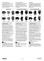
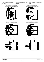
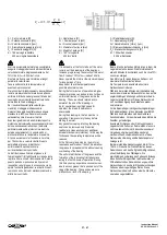
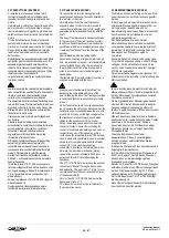
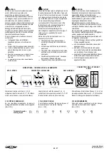
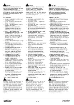
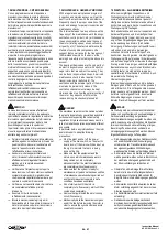
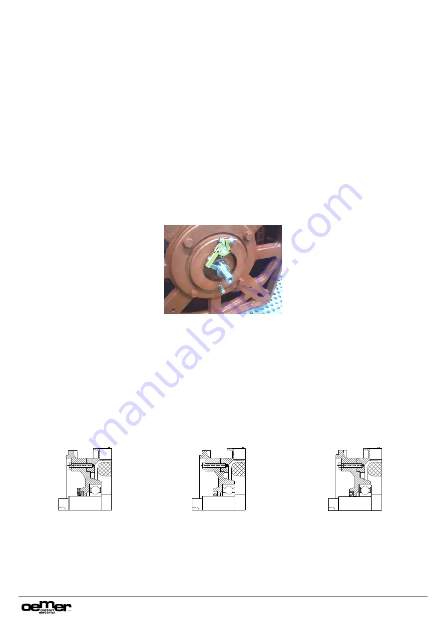
5.0.6 TENUTE MECCANICHE
Di seguito sono riportati alcuni esempi di tenute
meccaniche applicate all’albero del motore.
5.0.6 MECHANICAL SEALS
Below you will find some of the mechanical seals
used on the shaft.
5.0.6 MECHANISCHE WELLENABDICHTUNG
Nachstehend sind beispielhaft einige mechanische
Wellendichtungen für die Antriebswelle angeführt.
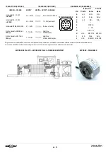
DUST PROTECTION NON-FRICTION RING
DUST PROTECTION SEAL (V-RING)
OIL SEAL


