


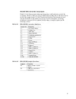


Hardware mounting
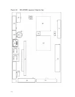
1. Use the standoffs, washers, and screws and place them in the nine holes on the
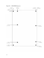
XE–800 SBC board. Refer to Figure 2–3 for the center-to-center mounting hole
dimensions and for the location of the designated holes used for mounting the
hardware.
WARNING!
All nine standoffs, screws and washers must be used to secure the
XE–800 SBC. The standoffs ensure full support of the board.
WARNING!
Verify that the washers and standoffs do not touch any of the
component pads adjacent to the mounting holes. Damage will occur
at power-up.
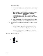
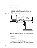
2.
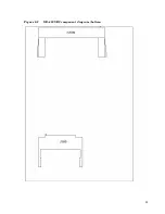
Connect a 5V power source to the XE–800 SBC. Refer to the Power Supply
Requirements section, page 25. The power supply connector is located at J8.
Refer to Figure 2–4 and Table 2–3.
Note
The +12V, –12V, and +3V signals are routed to the PC/104 and PC/104
Plus
bus
only.
WARNING!
Make sure the power supply is OFF when connecting the power
cable to the XE–800 SBC board. Damage to the XE–800 SBC may
occur if the power is ON when connecting the power cable.
WARNING!
Accidentally crossing the wires, i.e., pl5V wires into the
ground connector or the ground wires into the +5V connector will
damage the XE–800 SBC.
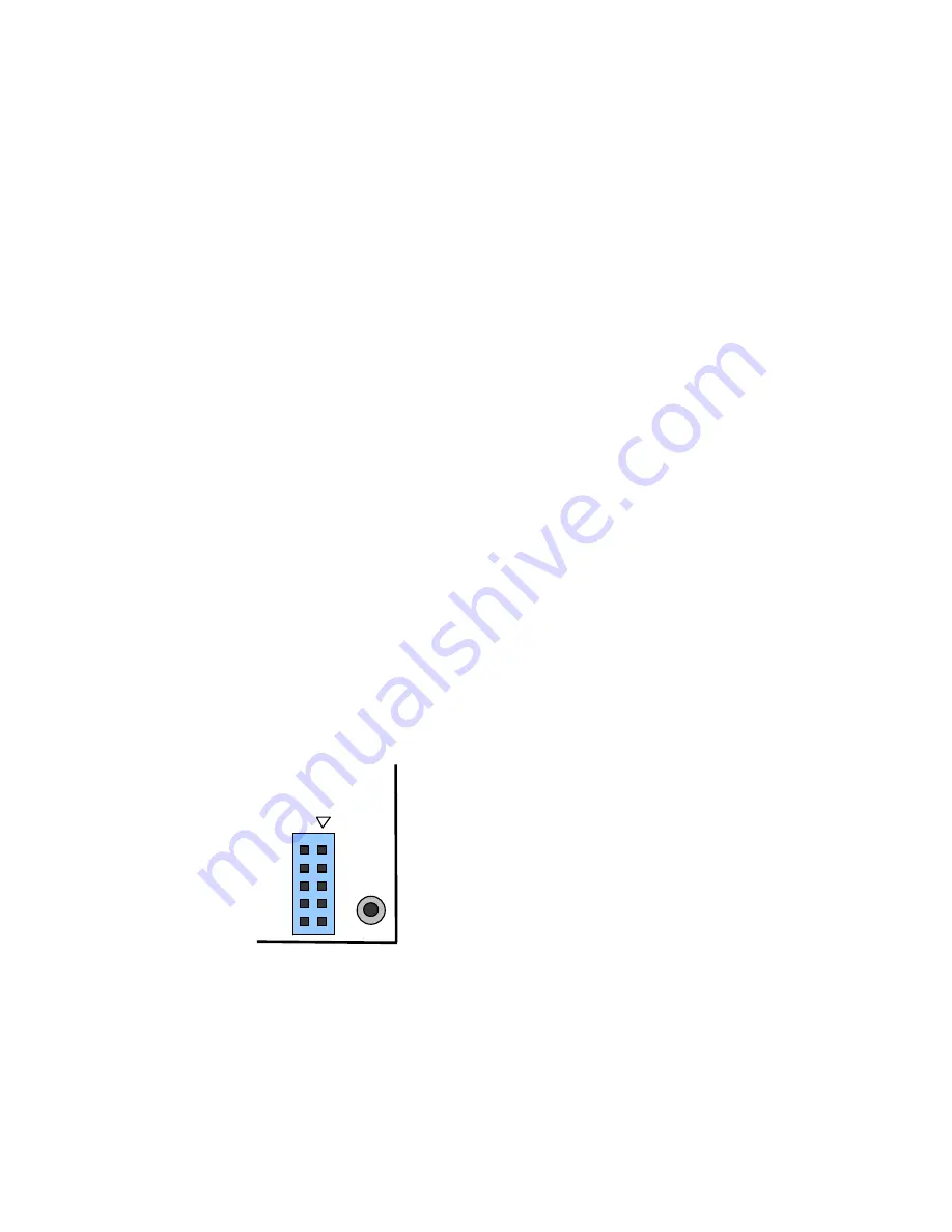
Figure 2–4
Power connector, J8
J8
1
5
6
10
24