


NXP Semiconductors
IMXRT500HDG
i.MX RT500 Hardware Design Guide
VDD_AO1V8
1
2
3
4
5
PMIC_MODE0/1
VDD1V8, VVD1V8_1
VDDIO_0, 1, 2, 3, 4
VDDA_BIAS
VDDIO_3(3.3V)
VDDCORE
RESETN
VDDA_ADC1V8, VREFP
ERR050716: VDDIO_x should be
powered at same time as VDD1V8
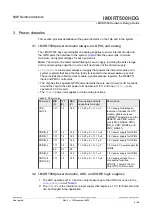
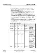
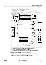
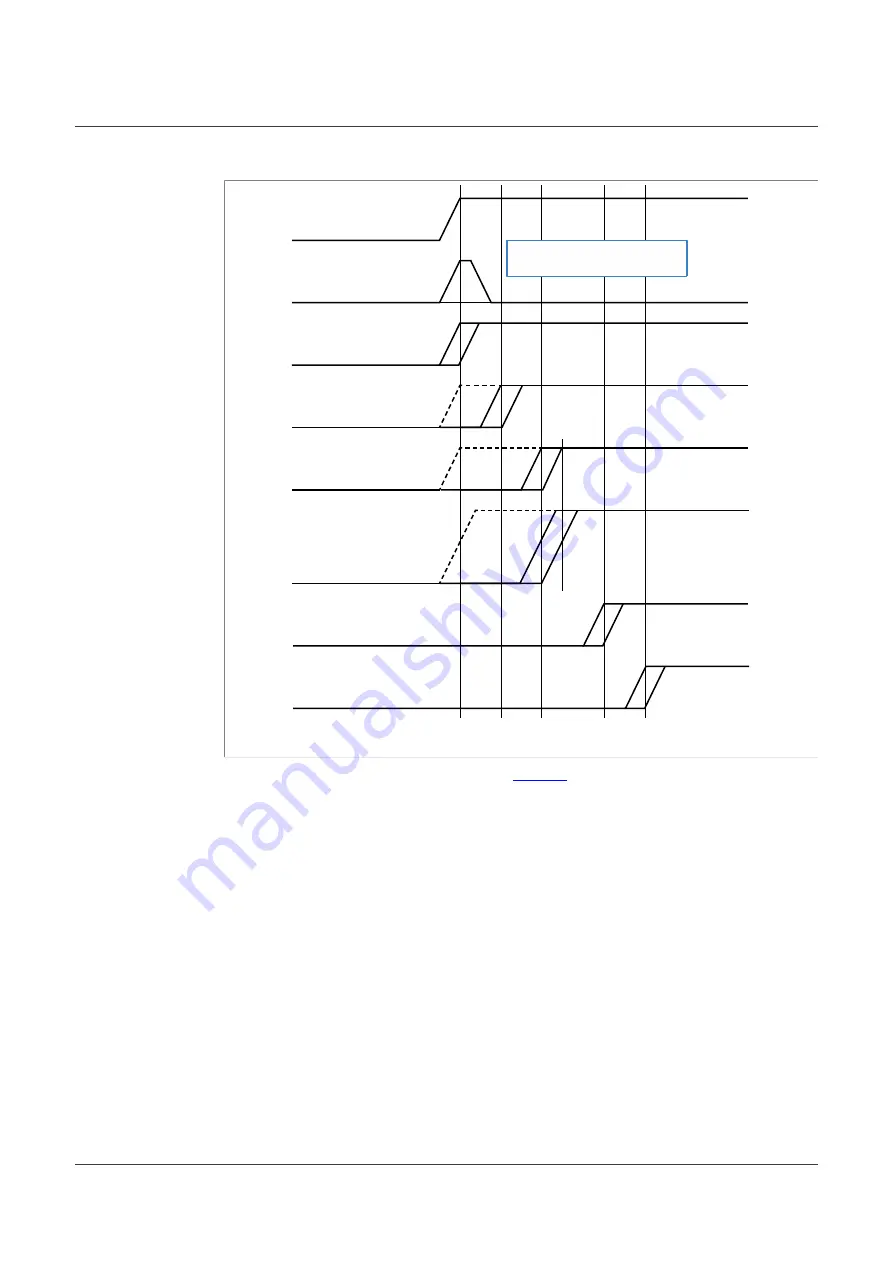
Figure 2. Power-on sequence
The power-on sequences are shown in the
are as follows:
1.
VDD_AO1V8
,
VDD1V8
, and
VDD1V8_1
should be powered first. If using PMIC, mode
pins are pulled-up to always-on supply until mode pins are active.
2.
VDDA_ADC1V8
and
VREFP
can be powered concurrently with
VDD_AO1V8
and
VDD1V8
or later.
3.
VDDIO_x
and
VDDA_BIAS
can be powered concurrently with
VDD1V8
range or later.
The delta voltage between
VDDIO_3
and
VDD1V8
must be 1.89 V or less when
VDDIO_3
is 3.3 V.
4. Power-up
VDDCORE
should not be ramped-up until after all the other supplies have
completed the rampup.
5. Hold
RESETN
low until
VDDCORE
is valid when PMIC is used. The only difference
when using internal
VDDCORE LDO
(
LDO_ENABLE
= 1) is that internal PMC releases
internal
RESETN
when
VDDCORE
is stable.
3.6 NXP PCA9420 PMIC
The NXP PCA9420 PMIC designed to be used with the i.MX RT500 and i.MX RT600
microcontrollers. This PMIC has two LDO regulators and two switch-mode regulators.
This PMIC is available in two small packages:
IMXRT500HDG
All information provided in this document is subject to legal disclaimers.
© 2022 NXP B.V. All rights reserved.
User guide
Rev. 0 — 15 November 2022
9 / 48


