


NXP Semiconductors
IMXRT500HDG
i.MX RT500 Hardware Design Guide
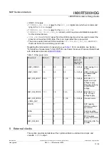
5.1 External clocks
The main crystal oscillator (
XTALIN
/
XTALOUT
) can drive crystals from 4 MHz to 32
MHz.
The main crystal oscillator can operate in low-power or high gain modes, while the
possible frequency range is 4 MHz to 32 MHz, the practical range is 5 MHz to 26 MHz
due to limitations of the on-chip PLLs.
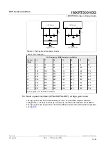
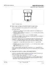
The Real-Time Clock (RTC) oscillator (
RTCXIN
/
RTCXOUT
) is strictly for:
•
32 kHz real-time clock (RTC) that can be used as a system clock and as timer clocks
•
Internal load capacitor selection 32.768 kHz crystals
It operates in low-power mode only and has internal load capacitor banks to tune the
crystal frequency, which can reduce component count.
CLKIN
and
CLKOUT
functions:
•
CLKIN
input clock – alternate input clock
•
CLKOUT
output clock:
–
Convenient output clock to measure crystal or system frequencies
–
Use to tune system and RTC oscillators
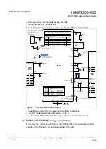
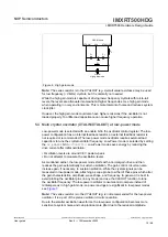
5.2 Main crystal oscillator (XTALIN/XTALOUT)
The main crystal oscillator uses the dedicated
XTALIN
and
XTALOUT
pins. This high-
frequency oscillator is used to source the PLLs and internal system clocks.
For the PLL multipliers, which limit the practical range of crystal frequencies, see
There is a limitation for the PLL crystal oscillator as it has a range from 5 MHz to 26 MHz
crystal, with a PLL multiplier range of 16 through 22, yielding a VCO frequency range of
80 MHz to 572 MHz. This oscillator has a low-power mode that starts up with a normal
gain and automatically adjusts to a lower gain to sustain oscillation. This mode provides
the lowest oscillator power dissipation but can be susceptible to noise if the system is
electrically noisy. The low-power oscillator configuration has its internal feedback resistor,
so an external feedback resistor is not necessary or recommended.
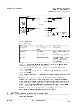
The high gain oscillator is a normal gain amplifier that does not adjust its drive level. The
high gain mode requires an external 1 M ohm feedback resistor. The high gain mode is
less susceptible to system noise but consumes more power.
Each configuration, low-power and high gain, requires external load capacitors on
the crystal pins, see
. For more details on oscillator load capacitance, refer to
This oscillator can be channeled to the
CLKOUT
output to measure the frequency and
trim the load capacitors as necessary. This oscillator can also be bypassed by driving an
external clock signal into the
XTALIN
pin.
IMXRT500HDG
All information provided in this document is subject to legal disclaimers.
© 2022 NXP B.V. All rights reserved.
User guide
Rev. 0 — 15 November 2022
13 / 48


