


NXP Semiconductors
IMXRT500HDG
i.MX RT500 Hardware Design Guide
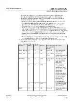
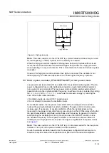
XTALOUT
XTALIN
V
SS
crystal
High gain mode
C
x
C
y
R
1
R
s
OSC Module
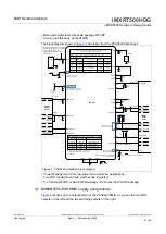
Figure 6. High gain mode
Note:
The series resistor is in the XTALOUT leg. A small value resistance may be used
for low frequency (<8 MHz) crystals, but it is normally not needed.
While the high gain mode is capable of driving lower frequency crystals with rail-to-rail
levels, the levels are attenuated somewhat at higher frequencies. Use high gain mode
when operating in noisy environments. This is more tolerant of noise and reduces system
clock jitter.
However, the high gain mode could also have higher emissions if the oscillator is not
loaded properly. Too little load capacitance can cause higher frequency operation.
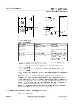
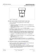
5.4 Main crystal oscillator (XTALIN/XTALOUT) at low-power mode
Low-power mode is selected with an enable bit in the oscillator control register. The low-
power configuration has an internal feedback resistor, an external feedback resistor is
not required or recommended. The low-power mode oscillator requires external load
capacitors to tune the crystal oscillator frequency. Low-Power mode is selected by setting
the
LP_ENABLE
bit in
SYSOSCCTL0
. Low-Power mode saves energy by reducing the
drive current after initial oscillation:
•
Oscillation levels are around 0.8 V peak-to-peak
•
Do not attempt to measure the oscillation levels
As mentioned earlier, the low-power mode starts with a normal gain drive and then
reduces the gain automatically to sustain oscillation. The gain control circuit can also
increase gain, if necessary, to sustain oscillation. While the crystal signals can be
measured in low-power mode, attaching a scope probe to either of these pins which alter
the gain characteristics, amplitude, wave shape, and frequency. In general, it is best to
avoid probing the oscillator pins (in any mode) and use the CLKOUT function to tune
the oscillator frequency. The low-power oscillator consumes microampere instead of
milliampere as in high gain mode, so power savings are significant in low-power modes,
.
Note:
The series resistor is in the XTALOUT leg, is not recommended for the low-power
oscillator. It is a part of the pierce oscillator circuit convention.
Due to the smaller oscillation waveforms, the low-power configuration becomes more
sensitive to system noise and can produce more jitter due to the reduced amplitude.
IMXRT500HDG
All information provided in this document is subject to legal disclaimers.
© 2022 NXP B.V. All rights reserved.
User guide
Rev. 0 — 15 November 2022
15 / 48


