


NXP Semiconductors
IMXRT500HDG
i.MX RT500 Hardware Design Guide
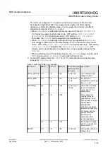
XTALOUT
XTALIN
V
SS
crystal
High gain mode
C
x
C
y
R
1
R
s
OSC Module
XTALOUT
XTALIN
V
SS
crystal
Low power mode
C
x
C
y
R
s
OSC Module
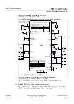
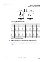
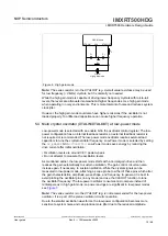
Figure 5. High gain and low-power modes
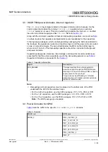
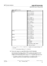
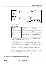
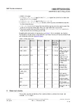
PLL frequency (MHz) based on multiplier
Crystal
(MHz)
16
17
18
19
20
21
22
4
64
68
72
76
80
84
88
5
80
85
90
95
100
105
110
8
128
136
144
152
160
168
176
10
160
170
180
190
200
210
220
16
256
272
288
304
320
336
352
20
320
340
360
380
400
420
440
24
384
408
432
456
480
504
528
26
416
442
468
494
520
546
572
32
512
544
576
608
640
672
704
VCO range is from 80 MHz to 572 MHz.
Table 8. PLL frequency
5.3 Main crystal oscillator (XTALIN/XTALOUT), at high gain mode
The high gain mode is the default setting at reset. The oscillator requires software
configuration, so it does not start up at power-up until firmware initializes the oscillator.
The high gain mode requires the 1 M ohm feedback resistor and external load capacitors,
.
IMXRT500HDG
All information provided in this document is subject to legal disclaimers.
© 2022 NXP B.V. All rights reserved.
User guide
Rev. 0 — 15 November 2022
14 / 48


