


NXP Semiconductors
IMXRT500HDG
i.MX RT500 Hardware Design Guide
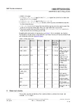
Boot mode
ISP2 pin
PIO3_29
ISP1 pin
PIO3_28
ISP0 pin
PIO1_15
Description
USB HID ISP low
high
low
Boot to ISP mode, using USB-HID class
FlexSPI Boot low
high
high
Boot from QSPI/Octal Flash devices
connected to the FlexSPI interface 0.
The i.MX RT5xx finds a valid image in an
external QSPI/Octal Flash device.
If there is no valid image found, the i.MX
RT5xx enters in recovery boot or ISP boot
mode.
SDIO 0
(eMMC)
high
low
low
Boot from an eMMC device connected to
SDIO 0 interface. The i.MX RT5xx finds a
valid image in the eMMC device. If there is
no valid image found, the i.MX RT5xx enters
in the ISP boot mode based on the value
of OTP DEFAULT_ISP_MODE bits (6:4,
BOOT_CFG [0]).
Reserved
high
low
high
Reserved
Serial ISP
(UART, I2C,
SPI)
high
high
low
The Serial Interface (UART, I2C, SPI) is
used to program OTP, external FLASH, or
eMMC devices
Serial
Download
high
high
high
Serial Master boot is used to download a
boot image over the serial interface (SPI
Slave or UART, I2C, USB-HID)
Table 13. Boot source
...continued
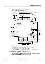
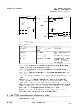
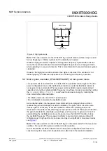
6.6 Physical ISP pins configuration on EVK board
Boot modes can be configured using the external boot configuration ISP switch SW7 on
the MIMXRT595-EVK board. The SW7 switch is configured to serial ISP mode as shown
in
. If serial ISP mode is implemented, weak pull-ups and strong pull-downs are
recommended.
R188
100 k
4
3
1
NO
R193
1 k
R192
1 k
R191
1 k
R189
100 k
R190
100 k
MCU_1V8
5
6
3
OFF
SLKSCRN: ISP2, ISP1 and ISP0
1
2
1
RT_PIO3_29_ISP2
RT_PIO3_28_ISP1
RT_PIO1_15_ISP0
SW7
418121160803
ON
0
Switch
Logic
Figure 12. EVK ISP configuration
For more details, see
.
IMXRT500HDG
All information provided in this document is subject to legal disclaimers.
© 2022 NXP B.V. All rights reserved.
User guide
Rev. 0 — 15 November 2022
24 / 48


