Nortek 2GIG GC3 Installation And Programming Manual Download Page 16

Copyright © 2019 Nortek Security & Control LLC

16

Installing the System

Install the GC3 Cellular Radio Module

The 2GIG GC3 Cellular Radio Module is a snap-in unit providing the GC3 Security & Automation System with 
communication to the Central Station for alarm signaling and delivering (Over-the-Air) OTA 

fi

 rmware updates to the GC3 

Panel. It also provides connectivity to the Remote Service Provider and 2-way voice communication. The module also 
includes a built-in antenna to provide a consistently strong communication signal.
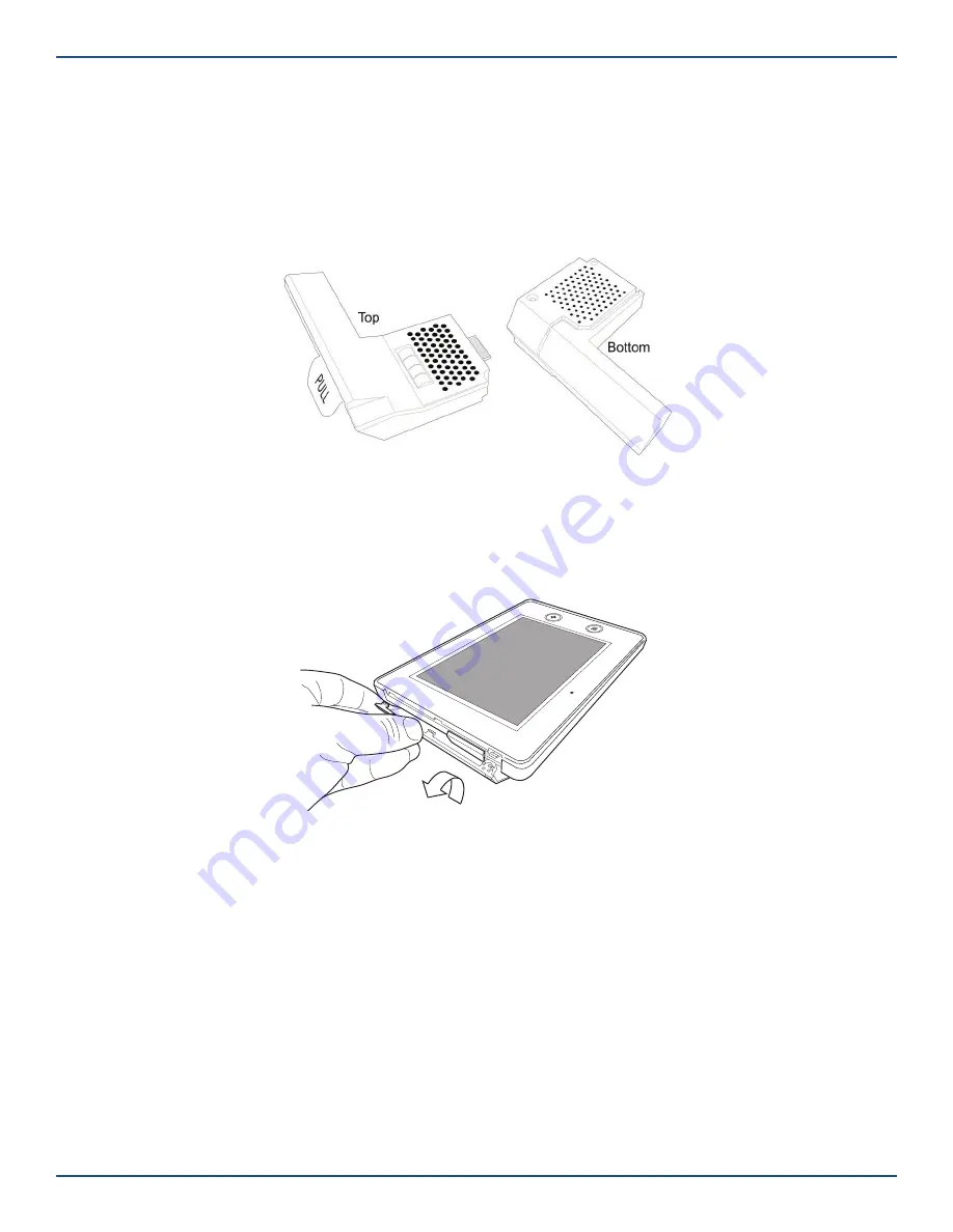
The illustration below shows you the top view and bottom view of the GC3 Cellular Radio Module.

GC3 Cellular Radio Module—Top & Bottom View

Install/Replace the Cellular Radio Module

System Completely Powered OFF

To install/replace the Cellular Radio Module into a system that is completely powered OFF:

1.  Remove the hinged door from the GC3 Control Panel.

Cellular Radio Module—Hinged Door

NOTE: 

If you are not able to remove the door, remove the door-lock screw for the Cellular Radio Module bay. See 

“(Optional) Lock/Unlock the Cellular Radio Module Door.”

2.  If you are replacing a module, pull the tab to remove the Cellular Radio Module. Otherwise, skip this step and 

continue with step 3.

3.  Insert the GC3 Cellular Radio Module until it clicks into place.
4.  Replace the hinged door.
5.  (Optional) Install the lock on the Cellular Radio Module bay door. See “(Optional) Lock/Unlock the Cellular Radio 

Module Door.”

6.  Power up the system and wait for the Control Panel to recognize the Cell Radio Module. (This may take up to 5 

minutes to complete.).

7.  After installing the Cellular Radio Module, go to the 

Installer Toolbox > System Con

fi

 guration > Radio Test

Then tap 

Start Radio Test

. When the test reads “Success,” tap 

Done

.

Summary of Contents for 2GIG GC3

Page 1: ...2GIG GC3 GC3e Security Automation System Installation and Programming Guide 10023748A X3 WARNING OWNER S INSTRUCTION NOTICE Not to be removed by anyone except occupant ...

Page 2: ...l including photocopying and recording for any purpose other than the purchaser s personal use without the written permission of Nortek Security Control Nortek Security Control 5919 Sea Otter Place Suite 100 Carlsbad CA 92010 USA 800 421 1587 Contents Introduction 5 About this Guide 5 Introduction to Smart Areas 5 Document Conventions 6 Technical Support 6 Planning the Installation 7 System Featur...

Page 3: ...22 Smart Home Controls require master code 57 Q24 Temperature display units 58 Q25 Swinger shutdown count 1 6 58 Q26 Cross sensor zones 99 100 58 Q27 Cross sensor timeout in seconds 10 120 58 Q28 Siren supervision time 58 Q29 CS lack of usage notification time in days 0 255 59 Q30 Radio modem network failure time in minutes 0 255 59 Q31 Radio network failure causes trouble 59 Q32 Radio network fai...

Page 4: ...68 Allow backlight always on demo mode 64 Q69 Smart Areas 64 Q70 Main Panel Sounder Follows 65 Q71 Security pin code length 65 Restore the Factory Default Settings 65 System Configuration Reference 66 Sensor Programming Reference 66 Panel Programming Reference 71 Features to Limit False Alarms 75 Image Sensor 76 Smart Home Settings Menu 76 Smart Home Settings Menu 76 Navigate to the Smart Home Set...

Page 5: ...ff limits to other people Disarming the garage while the homeowner is at work to allow a package to be delivered and stored safely on the premises Secure swimming pool or spa area to help reduce the risk of drowning accidents In California it is now required that newly built pools and spas include at least one safety measure including an alarm Smart Areas was designed for ease of setup and everyda...

Page 6: ...cate a situation which if not avoided could result in property damage equipment damage or data loss NOTE This notation is used to call attention to notable information that should be followed when installing servicing or using this product TIP This notation is used to call attention to helpful hints related to using the product Touchscreen Navigation This table describes the action words used to i...

Page 7: ...to the touchscreen s Home screen For more information see the GC3 Security Automation System Fingertip Guide Removable Faceplate A removable faceplate concealing a door lock for the Cellular Radio Module bay Microphone and Speaker A built in microphone and speaker provide clear 2 Way Voice communication during alarm events between users at the GC3 Panel and operators at the Central Station Cellula...

Page 8: ...ication protocol The GC3 Panel can be included and operated in any Z Wave network with other Z Wave certified devices from other manufacturers and or other applications All non battery operated nodes within the network will act as repeaters regardless of vendor to increase reliability of the network This device is a security enabled Z Wave Plus product that is able to use encrypted Z Wave Plus mes...

Page 9: ...l to electrical power PWR PWR1 hardwire loops wired zones ZONE1 ZONE2 solid state output BELL BELL and an open collector output OCL1 OCL2 NOTE Terminals are still marked as 2 Wire Smoke but 2 Wire smoke is not supported D Third Hand Hanging Strap A durable hanging strap provides installers with an extra hand when installing and servicing the GC3 Panel E Receiver Board The main receiver board F Pie...

Page 10: ... s sensors are operating properly it is important for 2GIG alarm dealers and system owners to ensure sensor batteries and wireless signals are tested at least once a year Depending on the specific installation systems may also be installed with one or more of the following 2GIG accessories Kits Keypads 2GIG Control Panel Desktop Kit 2GIG SP1 Keypad 2GIG SP2 Keypad 2GIG PAD1 Radios Antennas 2GIG Ce...

Page 11: ...tude range limitations have been reported while transporting the GC3 Panel Create the Installation Plan Before installing the system the first step is to create an installation plan for the premises Next determine the mounting location for all system components including the GC3 Panel and all sensors If the system includes wired sensors you will need to connect the wiring to the GC3 Panel s termin...

Page 12: ...possible signal strength To ensure the system and sensors are placed appropriately review the following illustration Control Panel Location Relative to Sensors CORRECT Centrally Locate Control Panel INCORRECT Sensors at the other end of the house might be too far away Control Panel Location Height CONTROL PANEL Basement CORRECT Mount Control Panel as HIGH above earth level as practical INCORRECT L...

Page 13: ...ry Protection Sensors Residential Installation CP ES DW PIR CP CONTROL PANEL DW DOOR WINDOW SENSOR PIR MOTION DETECTOR GB GLASS BREAK SENSOR PAD WIRELESS KEYPAD ES EXTERNAL SIREN LIVING DINING KITCHEN ENTRY BATH DEN GB BED DW DW DW DW DW DW DW DW FRONT AND SIDE DOOR SENSORS WITH ENTRY EXIT DELAY DW BED DW GARAGE GB PAD PIR DW DW DW MAIN AND SIDE GARAGE DOOR SENSORS WITH ENTRY EXIT DELAY diag gc3 b...

Page 14: ...4 m of a kitchen appliance furnace water heater or other source of combustion to minimize the risks of setting off a nuisance alarm Recommended Smoke Alarm Placement Early warning fire detection is best achieved when fire detection equipment is installed in all rooms and areas of the premises Equipment should be installed as follows Recommended Smoke Alarm Placement DINING KITCHEN BEDROOM BEDROOM ...

Page 15: ... the alarm sounder following the instructions provided with the sounder Once installed route the sounder s wiring to the appropriate screw terminals on the GC3 Panel s terminal block See Connect an External Alarm Sounder 5 Connect the Hardwire Loops If the property will be protected by any wired sensors route the hardwire loop wiring to the appropriate screw terminals on the GC3 Panel s terminal b...

Page 16: ...ellular Radio Module into a system that is completely powered OFF 1 Remove the hinged door from the GC3 Control Panel Cellular Radio Module Hinged Door NOTE If you are not able to remove the door remove the door lock screw for the Cellular Radio Module bay See Optional Lock Unlock the Cellular Radio Module Door 2 If you are replacing a module pull the tab to remove the Cellular Radio Module Otherw...

Page 17: ...io Module bay is locked remove the faceplate and then move the door lock screw to the UNLOCK position See Optional Lock Unlock the Cellular Radio Module Door 5 Remove the hinged door from the GC3 Control Panel Cellular Radio Module Hinged Door 6 Pull the tab to remove the Cellular Radio Module 7 Insert the GC3 Cellular Radio Module until it clicks into place 8 Optional Install the lock on the Cell...

Page 18: ... cover and remove the cover Cellular Radio Module Remove Cover 6 Disconnect the antenna from the Cell Radio Module PCB and remove the antenna 7 Connect the external antenna to the Cell Radio Module PCB Cellular Radio Module Route Antenna Cable 8 Route the external antenna cable out through the slot on the bottom of the module 9 Replace the Cellular Radio Module cover and secure with the three scre...

Page 19: ...o Module Antenna 3 Route the antenna cable through the wiring cutout on the GC3 Panel s backplate 4 Route the antenna cable and attach it to the connector on the Cellular Radio Module Optional Lock Unlock the Cellular Radio Module Door The Cellular Radio Module fits into the bay on the side of the GC3 Panel and features a built in door lock under the faceplate The Control Panel ships with the door...

Page 20: ...hen gently pry the faceplate from the chassis GC3 Panel Removeable Faceplate 2 Remove the door lock screw from the UNLOCK position on the right GC3 Panel UNLOCK position 3 Install the screw into the LOCK position on the left This locks the hinged door on the GC3 Control Panel GC3 Panel LOCK position 4 Snap the faceplate back on the GC3 Control Panel Mount the GC3 Panel s Backplate ...

Page 21: ...d on the top of the panel Remove the bottom of the backplate first 5 Press the backplate flush against the wall at the mounting location NOTE The backplate has a built in level to ensure the GC3 Panel hangs straight GC3 Panel Built in Level 6 Use the backplate as a template to mark the location of the wiring cutout Then cut a slot in the dry wall for the AC power cord and other electrical wiring i...

Page 22: ...GC2 mounting screws 11 Attach the GC3 Panel s third hand hanging strap to the hook at the bottom of the backplate Optional Desktop Kit Optional Desktop Kit NOTE If mounting the GC3 Panel on a wall is not an option the 2GIG Desktop Kit can be purchased for use with the GC3 Security Automation System This is an accessory that lets one mount the GC3 Panel on a stand that can be placed on a flat surfa...

Page 23: ...block IMPORTANT The GC3 Panel is designed to connect to Solid State Relay sounders only To avoid damage to the output do NOT connect an Electromechanical Relay bell to the BELL or BELL position on the GC3 Panel s terminal block In addition bell output is only provided when the GC3 Panel s power supply is connected to an AC power source To connect an external alarm sounder to the GC3 Panel 1 Instal...

Page 24: ...ly Closed N C circuits This means the circuit on the contact switch is closed when the magnets are aligned on the door window contact When armed the GC3 Panel activates an alarm signal it detects that the door or window is no longer in the normally closed state Normally Open N O Used for Normally Open N O circuits This means the circuit on the contact switch is open when the magnets are aligned on...

Page 25: ...C3 Panel is to use the system s terminal block This requires you securely fasten 2 conductor power wire not supplied to the appropriate PWR PWR screw terminals GC3 Panel Terminal Block To connect the power supply to the GC3 Panel 1 Locate an unswitched wall outlet for the plug in power supply Do NOT connect the power supply to the outlet at this time 2 Route 2 conductor power wire from the plug in...

Page 26: ... is to use the optional barrel connector To connect the power supply s barrel connector to the GC3 Panel 1 Locate an unswitched wall outlet for the plug in power supply Do NOT connect the power supply to the outlet at this time 2 Route the power wire from the plug in power supply through the wiring cutout on the GC3 Panel s backplate 3 Plug the barrel connector into the DC power adapter barrel jac...

Page 27: ...necting the Power Supply Plug in 14 VDC 1 7 AMP Switching Power Supply Piezo Siren Supervised Bell Output 14 VDC 500 mA Maximum 2 2 K Normally Closed Contact 2 2 K Normally Closed Contact UL NOTE Wiring for all wired sensors and annunciators must use UL Listed low voltage Class 2 or better grade wire Sensor and display voltages must comply with Class 2 low voltage requirements End of Line Resistor...

Page 28: ...ters 1 CLASS 2 14 VDC Power Input Only provides power when the GC3Panel s power supply is connected to an AC power source 2 CLASS 2 14 VDC Power Input 3 CLASS 2 Ground Low Side Hardwire Zone 4 CLASS 2 Bell 5 CLASS 2 Bell 6 CLASS 2 Hardwire Loop Zone 1 7 CLASS 2 Hardwire Loop Zone 2 8 CLASS 2 Ground Lowside Hardwire Zone 9 CLASS 2 Transmit RS232 TX Image Sensor 10 CLASS 2 Receive RS232 RX Image Sen...

Page 29: ...he outlet at this time Always complete all system wiring and then secure the backplate to the GC3 Panel before connecting its power supply to the outlet Hang the GC3 Panel To hang the GC3 Panel on the mounting plate 1 Ensure all installed wiring is securely fastened 2 Ensure the connector to the Piezo Sounder is secure GC3 Panel Interal Siren Speaker Connector 3 Ensure the connector to the interna...

Page 30: ... wall bracket and connect the AC power supply 1 Locate an unswitched wall outlet for the plug in power supply Do NOT connect the power supply to the receptacle 2 Peel the adhesive backing off the power supply s retaining wall bracket and attach it to the receptacle 3 Secure the bracket to the wall using the fastening screw 4 Spread the ears of the retaining bracket apart Then plug the power supply...

Page 31: ...pdate Available from USB Device Note Firmware Update Available from USB Device message appears for approximately 10 seconds If you are not able to tap the Update button in the message in that time you can alternately tap the System Settings button or the Firmware Update button in the system icons area Then enter the Master User Code and then tap Firmware Update to start the update process The GC3 ...

Page 32: ...or one of the menus tap the logo in the top right corner Then enter your code to access the Installer Toolbox OR At the Home screen tap System Settings Then enter your code and tap Installer Toolbox Navigate to the Installer Toolbox Menu The Installer Toolbox menu is shown below Installer Toolbox Window Broadband The built in WiFi module and optional Ethernet module allow for broadband connection ...

Page 33: ...ill be displayed 3 Tap Network to connect to Select Wireless Network 4 Enter network password and tap Next Keyboard Entry Screen You will see the IP Address and other network information Wireless Network Setup Note This WiFi connection only connects the panel to the local network WiFi is required for connecting wireless touchscreens to the GC3 Panel Selection Buttons Refresh Network Options Tappin...

Page 34: ...n Other Network Join Other Network 2 Enter network SSID 3 Select authentication type used by the network 4 Enter password Forget Network Forget Network Tapping Forget Network disconnects the GC3 Panel from the wireless network and erases the password so that it will not automatically reconnect to the network Wired Ethernet Attaching to a Wired Network Ethernet Network Attach to a Wired Network 1 N...

Page 35: ...nal Press Edit icon next to Password enter new password Optional Press Edit icon next to IP address the last two octets of the Access Point can be changed to customize setup 4 After any edits have been made press Save Access Point Settings to save any configuration settings Note Make a note of SSID and Password for use in WiFi setup of SP1 and SP2 keypads 5 Tap Setting Up a Static IP Address By de...

Page 36: ...st Testing the Broadband network connection 1 Navigate to the Installer Toolbox menu and tap Network Test 2 Tap Start 3 The Network test will run If successful green dots will appear under each test LAN Internet and Backend If a failure is detected a red dot will appear under the test LAN Connection to Local Network Internet Connection to Internet Backend Connection to Alarm com NOTE Correct any n...

Page 37: ...e wireless zone to edit 1 On the left side of the Wireless Zones screen swipe up or down to move through the list of zones 2 Tap one of the available zones to highlight it Pairing with a System This feature allows the panel to pair with approved third party systems 1 Navigate to the Installer Toolbox and tap System Pairing Tap System Pairing Mode 2 Press the button to start the pairing process Sys...

Page 38: ...ect a Sensor Type above you must also select the Sensor Equipment Type If you selected a different Sensor Type skip this step and continue with Step 4 Select the Equipment Code below 1 At the Wireless Zone screen highlight Sensor Equipment Type 2 Under Sensor Equipment Type choose Contact or Emergency or Motion Available options vary depending on the selected Sensor Type 3 Tap Step 4 Select the Eq...

Page 39: ...e 7 digit TX ID on the sensor or peripheral Then tap Accept 5 Tap Step 6 Smart Areas Assignment Select a Smart Area Assignment 1 At the Wireless Zone screen highlight Smart Areas Assignment 2 Under Smart Areas Assignement choose a Smart Area Partition for the zone 3 Tap Step 7 Choose the Equipment Age Next choose the equipment age 1 At the Wireless Zone screen highlight Equipment Age 2 Under Equip...

Page 40: ... of time the system waits for it to initiate the digital transmission when an alarm condition is triggered see Q39 Alarm abort window transmission delay When set to OFF the dialer delay is not used Note This setting does not apply to CO or smoke alarms 1 At the Wireless Zone screen highlight Dialer Delay 2 Under Dialer Delay choose Enabled or Disabled 3 Tap Wireless Zone Screen Transmission Delay ...

Page 41: ...rvised 2 Under Sensor Supervised choose Enabled or Disabled 3 Tap Wireless Zone Sensor Supervised Step 13 Choose a Chime Next select the desired chime for the sensor or peripheral 1 At the Wireless Zone screen highlight Sensor Chime 2 Choose the desired chime from the Sensor Chime list The default setting is Disabled Wireless Zone Sensor Chime Next Steps You have finished programming a wireless zo...

Page 42: ...e Next select the appropriate sensor type for the sensor or peripheral being programmed 1 At the Wired Zone screen highlight Sensor Type 2 Tap to expand the list 3 Tap to select the appropriate sensor type from the list Wired Zone Sensor Type If you selected 04 Interior Follower 06 24 Hour Silent Alarm 07 24 Hour Audible Alarm 08 24 Hour Auxiliary Alarm 10 Interior with Delay or 23 No Response Typ...

Page 43: ...act programmed as NC goes into the NO state the change from NC to NO would trigger an alarm Normally Open NO Sends an alert signal to the security system when the sensor s circuit is no longer in the NO state For example if the security system was armed and a wired door window contact programmed as NO goes into the NC state the change from NO to NC would trigger an alarm End of Line Resistor EOL C...

Page 44: ...ter up to six words to create a voice descriptor 6 Tap Done Voice Descriptor Touchscreen Keypad Entry 7 Review the voice descriptor Review Voice Descriptor 8 Tap Step 8 Enable or Disable Sensor Reports Next turn the sensor reports feature ON or OFF When enabled the feature is ON and the system sends a report to the Central Station when the sensor or peripheral is triggered When disabled the featur...

Page 45: ...eyfobs per system To begin zone programming navigate to the Installer Toolbox See Navigate to the Installer Toolbox Then tap System Configuration Keyfobs NOTES When programming eSensors Wireless Keyfobs the equipment code must match the sensor being installed See page 68 for eSensor Equipment Codes eSeries sensors are only compatible with the GC3e panel System Configuration Menu This reveals the Ke...

Page 46: ... affixed to the product and or its packaging To enter the number choose one of these options Touchscreen Keypad Entry Use the touchscreen keypad to type the TX ID into the system OR Learning Mode Entry Place the GC3 Panel into Learning Mode and then trigger the keyfob to transmit the TX ID from the keyfob to the GC3 Panel 1 At the Keyfob screen highlight Serial Number 2 Place the panel into Learni...

Page 47: ...reen highlight Equipment Age 2 Under Equipment Age choose New or Existing Keyfob Screen Equipment Age 3 Tap Step 7 Enable the Emergency Key Next choose whether simultaneously pressing the Arm Away and Disarm buttons on the keyfob triggers an emergency alarm 1 At the Keyfob screen highlight Emergency Key 2 Under Emergency Key choose one of these options Disabled This turns the emergency key functio...

Page 48: ...bulary word above the touchscreen keypad to select it Keyfob Programming Word Entry Touchscreen 5 Repeat the steps above to enter the desired phrase for the keyfob Enter up to six words to make a voice descriptor 6 Tap Done 7 Review the voice descriptor Keyfob Programming New Voice Descriptor 8 Tap Step 10 Enable or Disable Arm with No Entry Delay Next enable or disable the Fob Arm with No Delay o...

Page 49: ... programming a keyfob You can now choose one of these options To program another keyfob tap Next Keyfob and repeat the programming steps for another keyfob The system keeps track of all your programming changes and prompts you to permanently save all your changes as a group when you exit the System Configuration menu To program the next keyfob tap uu This button becomes visible and available only ...

Page 50: ... list Keypad Screen Equipment Code Tip You can alternatively use the touchscreen keypad to enter the four digit Equipment Code See Equipment Codes 4 Tap Step 4A Pair SP1 or SP2 Pair the SP1 or SP2 keypad to the system If SP1 or SP2 was selected in Equipment Code this option will show as Device ID NOTE If programming a PAD1 the option will show as Serial Number follow Step 4B Before Pairing SP1 or ...

Page 51: ...tion on how to trigger it When the panel receives the TX ID the Sensor Received message appears 4 Verify that the TX ID on the touchscreen matches the one on the product 5 Tap Accept Keypad Screen Accept Serial Number Tip Instead of placing the GC3 Panel into Learning Mode you can alternatively use the touchscreen s keypad to manually enter the 7 digit TX ID 6 Tap Step 5 Selecting the Smart Area A...

Page 52: ...bled or Disabled Keypad Screen Emergency Keys 3 Tap Step 8 Select a Voice Descriptor 1 At the Keypad screen highlight Voice Descriptor 2 On the touchscreen tap Edit Voice Descriptor to reveal the touchscreen keypad Keypad Screen Edit Voice Descriptor 3 On the touchscreen keypad enter the first few letters of the desired vocabulary word 4 Tap the matching vocabulary word above the touchscreen keypa...

Page 53: ...p Reset Keypad To permanently save the settings you just programmed tap Return to System Configuration Then tap At the Confirm Changes screen tap Save The following illustration is an example of the Wireless Zones screen Example Wireless Zones Screen 2 At the Reset Zone message verify that you are deleting the desired item Then tap Reset Reset Zone Message This restores the factory default setting...

Page 54: ...gh a door Typically the primary entrance programmed as an Exit Entry 1 door uses this time When the user enters the premises the countdown timer starts The GC3 Panel beeps once every two 2 seconds during the countdown Panel Programming This section details the Panel Programming questions A dagger indicates a factory default setting A double dagger indicates a default setting for compliance with AN...

Page 55: ... OFF Stay On Line Turns the feature ON and automatically enables the 2 Way Voice feature after a burglary alarm Stay On Line Including Fire CO Alarms Turns the feature ON and automatically enables the 2 Way Voice feature after a burglary fire and or carbon monoxide alarm When the Control Panel connects with the operator it will beep once every six seconds The beep alternates between two tones and ...

Page 56: ...ON any occupant can arm the system When OFF only persons who know an active four digit user code can arm the system Choose one of these options Enabled Turns the feature ON and does not require occupants to enter a user code to arm the system Disabled Turns the feature OFF and requires occupants to enter an active four digit user code to arm the system Q14 Auto stay Turns the system s Auto Stay fe...

Page 57: ...gures the system to activate a unique sound when the system is armed disarmed with a keyfob This feature can be assiged individually for each Smart Area Smart Areas feature must be enabled Q69 for settings for S2 S4 to affect the system When enabled the GC3 Panel s speaker emits one 1 beep when arming and two 2 beeps when disarming the system with a keyfob If an external alarm sounder is installed...

Page 58: ...two sensors in the cross sensor zone is violated the system automatically transmits a trouble report about the violated sensor to the Central Station If both sensors in the cross zones are violated within the amount of time specified in Q27 Cross sensor timeout in seconds 10 120 the system activates an alarm and also transmits an alarm report to the Central Station NOTE Carbon Monoxide Detectors a...

Page 59: ... feature OFF The GC3 Panel will not display a visual indicator after a cellular radio network failure NOTE Regardless of the setting selected here a radio network failure will always be logged in the System History Once the network connection is restored the system automatically clears the visual indicator A record of the trouble alert condition is stored in the System History Q32 Radio network fa...

Page 60: ...el time in minutes 5 255 Choose one of these options Enabled Turns the feature ON This displays an alert message notifying the user that an alarm cancellation report was sent to the Central Station For compliance with ANSI SIA CP 01 2010 the default setting for this feature is enabled Disabled Turns the feature OFF The system will not display an alert message when a cancellation report is sent to ...

Page 61: ...s recorded in the system s Alarm History Choose one of these options Enabled Turns the feature ON Disabled Turns the feature OFF For compliance with UL 985 Household Fire Warning System Units this setting must be disabled Q43 Z Wave siren mode Configures the system to sound any Z Wave sirens that have been added to the network Choose one of the options Sound for Burglary and Fire CO Configures the...

Page 62: ...bled The system does not transmit a report to the Central Station Q49 Trouble reports to CS Configures the system to transmit trouble reports to the Central Station when the system detects that any sensor encounters a trouble condition NOTE This setting does not affect trouble reports caused by Control Panel conditions It only affects trouble reports caused by sensors Choose one of these options E...

Page 63: ...fter a low battery condition for a sensor is restored Choose one of these options Enabled The system transmits a report to the Central Station Disabled The system does not transmit a report to the Central Station Q59 System disarmed reports to CS Configures the system to transmit a report to the Central Station when the system is disarmed by a user The report includes the keyfob or user code that ...

Page 64: ...nsors will remain bypassed when the system is disarmed Q66 Force bypass reports Configures the system to transmit a report to the Central Station when a user force bypasses a sensor while the system is armed You have these options Enabled The system transmits a report to the Central Station Disabled The system does not transmit a report to the Central Station NOTE Forced bypassed sensors are alway...

Page 65: ... system will prompt to resolve the conflicts Conflicts can be resolved by defaulting the user codes or changing the existing pin codes so that no first four digits of the pin codes are the same Soft Reset A soft reset lets you select which settings to restore back to the factory defaults To perform a soft reset 1 Navigate to the Installer Toolbox screen 2 Tap Restore Defaults 3 At the Restore Defa...

Page 66: ...r This sensor type is for interior sensors such as motion detectors interior doors and other sensors that detect human presence inside the protected premises This type of sensor is called a follower due to its action when the system is armed in the Away mode After the exit delay expires and the system is armed if an interior follower sensor is triggered an instant alarm will occur If an exit entry...

Page 67: ...This sensor type is always active and cannot be bypassed 16 24 Hour Fire Verification This sensor type is continuously armed 24 hours a day A sensor programmed to this type can trigger the local alarm fire sounder and the bell output regardless of the mode the system is in This sensor type is typically used for wireless smoke detectors This sensor type is always active and cannot be bypassed For v...

Page 68: ...at the panel Equipment Code Required for all wireless zones keyfobs and keypads Equipment Code Wireless Zones Equipment Codes 0000 Other 0862 2GIG Thin D W Surface Contact 0863 2GIG Recessed Door Contact 0869 2GIG PIR with Pet Immunity 0864 2GIG Glass Break Detector 0865 2GIG Outdoor Door Window Sensor 0895 SMKT2 345 GE Smoke Heat Detector USA Canada 1058 2GIG Smoke Detector 0872 SMKE1 345 Smoke D...

Page 69: ...c Code A Abort 002 AC 003 Access 004 Alarm 005 And 006 Announcement 007 Apartment 266 Area 008 Arm 009 Armed 010 Arming 011 At 012 Attic 013 Audio 014 Auto 015 Automation 016 Auxiliary 017 Away 018 B Baby s 019 Back 020 Balcony 256 Basement 021 Bathroom 022 Battery 023 Bedroom 024 Bell 272 Bonus 025 Boy s 273 Break 026 Button 027 Bypass 028 Bypassed 029 C Cabinet 030 Camera 274 Cancel 031 Carbon M...

Page 70: ...nder 209 South 210 Space 211 Spare 212 Stairs 213 Star 214 Status 215 Stay 216 Stop 217 Storage 218 Study 219 Sump 220 Sun 283 Sunroom 263 Supervision 221 Switch 286 System 222 T Tamper 223 Temperature 224 Ten 225 Terminated 226 Theater 284 Thermostat 227 Third 228 Thirteen 229 Thirty 230 Three 231 To 232 Tool 233 Transmitted 234 Transmitter 235 Trouble 236 Turn 237 TV 268 Twelve 238 Twenty 239 Tw...

Page 71: ... of Defaults Allow Reset of All Defaults Q4 Exit delay in seconds 45 120 45 120 Seconds 60 Seconds Q5 Entry delay 1 in seconds 30 240 30 240 Seconds 30 Seconds Q6 Entry delay 2 in seconds 30 240 30 240 Seconds 45 Seconds Q7 Remote services provider None Alarm com Alarm com Q8 2 way voice Disabled Stay online Stay online including fire and CO alarms Stay online Q9 Disable siren after two way audio ...

Page 72: ...eit Celsius Fahrenheit Q25 Swinger shutdown count 1 6 1 6 Trips 2 Trips Q26 Cross sensor zones 99 100 Enabled Disabled Disabled Q27 Cross sensor timeout in seconds 10 120 10 120 Seconds 10 Seconds Q28 Siren supervision time Disabled 15 Seconds 30 Seconds 45 Seconds Disabled Q29 CS lack of usage notification time in days 0 255 0 255 Days 7 Days Q30 Radio modem network failure time in minutes 0 255 ...

Page 73: ...ated on Radio Fault 06 Activated on Burglary Alarm 07 Activated on Fire Alarm 08 Activated on Any Alarm 09 Activated on Any System Trouble 11 Follows Internal Sounder Alarm 12 Follows Exit Entry Beeps 11 Follows Internal Sounder Alarm Q45 Open collector 2 output 00 Disabled 01 Activated when Armed 02 Activated when Disarmed 03 Activated on FTC 04 Activated on Supervision 05 Activated on Radio Faul...

Page 74: ...rmed reports to CS Enabled Disabled Disabled Q60 System armed reports to CS Enabled Disabled Disabled Q61 Alarm restore reports to CS Enabled Disabled Disabled Q62 Smart test reports Enabled Disabled Disabled Q63 RF jam causes trouble Enabled Disabled Disabled Q64 System tamper causes trouble Enabled Disabled Enabled Q65 Auto unbypass for manual bypass Enabled Disabled Enabled Q66 Force bypass rep...

Page 75: ...System Acknowledgment Alert Keyfob Disarming After Alarm Keyfob Arm Disarm Confirmation Q18 Alert on disarm with keyfob after alarm Q18 Alert on disarm with keyfob after alarm 4 2 4 4 Remote Arming Key Fob Arming Q18 Alert on disarm with keyfob after alarm 4 3 4 5 Remote Disarming Key Fob Arming Q19 Keyfob arm disarm confirmation 4 2 5 1 Abort Window Abort Window Dialer Delay Q39 Alarm abort windo...

Page 76: ...s menu is only available to installers The Smart Home Settings menu provides installers with access to a variety of Z Wave settings for the GC3 Security Automation System Installers can configure the system to give the Master User permission to access the Smart Home Settings menu users who know the Master User code can access a variety of Z Wave settings for the GC3 Security Automation System Note...

Page 77: ...Add Devices Now 3 Walk to and trigger the device For example if you are adding a Z Wave light bulb turn the light bulb ON Tip Typically you can trigger a device on the network by either powering the device OFF ON pressing a button once or twice or flipping a switch on the device Every device is different When the system discovers a device the New device found and Adding device message appears Addi...

Page 78: ...t desired device and then renaming it as needed 8 Tap to return to the Smart Home Settings menu Remove a Device To remove a device from the network 1 Navigate to the Smart Home Settings menu See Navigate to the Smart Home Settings Menu 2 At the Smart Home Settings menu tap Remove Devices Smart Home Settings Remove Devices The Listening for Devices to Remove screen appears Listening for Devices to ...

Page 79: ...ome Settings menu See Navigate to the Smart Home Settings Menu 2 At the Smart Home Settings menu tap Check Network Smart Home Settings Check Network 3 At the Check Network screen tap Start Check Network Start The system scans the network for unresponsive nodes and indicates the status of each scanned node Check Network Status 4 When the Check Network is complete you can see the status of nodes in ...

Page 80: ...vices function lists all Z Wave devices in the Control Panel network and provides the following options depending on the type and current status of a device Configure Hide Unhide Identify Remove Rename Replace To view all network devices and access these options 1 Navigate to the Smart Home Settings menu See Navigate to the Smart Home Settings Menu 2 At the Smart Home Settings menu tap View All De...

Page 81: ... Unhide option determines whether or not a device appears on Smart Home Control screens To hide a device on Smart Home Control screens 1 Tap the menu button next to the device and tap Hide Smart Home Devices Hide A confirmation screen appears Smart Home Devices Hide Confirmation 2 Tap Hide to prevent the device from appearing on Smart Home Control screens The device appears in gray text on Smart Ho...

Page 82: ...Smart Home Devices Identify Remove This option lets you remove a non communicating node from the system This option only appears for a device that is not communicating with the system Note Non communicating devices are indicated by an alert icon To remove a non communicating node from the system 1 Tap the menu button next to the non communicating device and tap Remove Smart Home Devices Remove A c...

Page 83: ...other mesh network settings This makes it easier to replace a device that is no longer working and is only available for a non communicating device Note Non communicating devices are indicated by an alert icon To replace a non communicating device 1 Tap the menu button next to the non communicating device and tap Replace Smart Home Devices Non Communicating Device 2 Tap Replace Smart Home Devices ...

Page 84: ...vices to communicate directly with each other To associate Z Wave devices 1 At the Home screen tap System Settings Home System Settings 2 Enter the Master User Code to access the System Settings screen 3 At the System Settings menu tap Smart Home Settings on both Control Panels System Settings Smart Home Settings 4 At the Smart Home Settings menu tap Device Association Smart Home Settings Advanced...

Page 85: ...he network and to reset the controller to its factory default state Note Use this procedure only in the event that the network primary controller is missing or otherwise inoperable To reset the controller 1 Navigate to the Smart Home Settings menu See Navigate to the Smart Home Settings Menu 2 At the Smart Home Settings menu tap Advanced Settings Smart Home Settings Advanced Settings 3 At the Adva...

Page 86: ...y controller this process is also called copy or replication When the GC3 Panel acts as a secondary controller devices can only be added to or removed from the Z Wave network at the primary controller Other than that all functions are available to either controller To add the GC3 Panel as a secondary controller for an existing Z Wave network 1 At the existing controller add the GC3 Panel to the Z ...

Page 87: ... disabled for 30 minutes or until you tap the Re enable Sounder button Perform a Walk Test After installing the system sensors and peripherals perform a walk test to ensure proper console operations and to test wireless reception and signal strength To open the Walk Test menu navigate to the Installer Toolbox Then tap Walk Test To test wireless reception and signal strength tap Sensors Test Then w...

Page 88: ...st to check the cell signal strength confirm the serial number of the module and view other information about the cellular radio connection This is a helpful tool to use when troubleshooting the installation To open the Radio Test menu navigate to the Installer Toolbox Then tap Radio Test At the Radio Status screen tap Start Radio Test When the test is complete A Success message indicates the modu...

Page 89: ...reen tile System Settings Screen Tile 11 In the Screen Saver section select DEMO MODE Screen Demo Mode 12 Press the edit icon in the Screen Saver section 13 Set the volume for the video playback Demo Mode Video Volume 14 Tap to exit Notes The demo video will play when the screen times out and will then return to the home screen It will then repeat each time the screen times out To turn off the dem...

Page 90: ...Copyright 2019 Nortek Security Control LLC 90 THIS PAGE LEFT INTENTIONALLY BLANK ...

Page 91: ...sposal will help to conserve natural resources and ensure that it is recycled in a manner that protects human health and the environment For more information about where you can drop off your waste equipment for recycling please contact your local city office or your household waste disposal service or the shop where you purchased the product WARNINGS Limitations of Alarm Products This product sho...

Page 92: ...Copyright 2019 Nortek Security Control LLC A L A R M D E A L E R I N F O R M A T I O N Company Name Your Account Number Installation Date 10023748A X3 ...

Reviews: