SDS Meters
3
Part 1009912E
E
2005 Nordson Corporation
Description
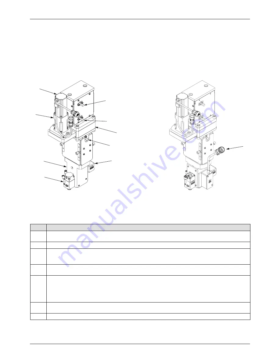
See Figure 1. The SDS meters are designed for
high-speed application of single-component materials. A
closed-coupled dispense valve and electric servo
controlled metering allows for accurate dispensing.
Six SDS meters are available:
S
40- and 90-cc; unheated
S
40- and 90-cc; 120v and 240V heated
Table 1 lists the major SDS meter components.
1
5
2
6
7
4
3
3
3
40-CC SDS Meter
Heated 40-CC SDS Meter
8
Figure 1
Typical SDS Meters
Table 1 SDS Meter Components
Item
Description
1
Servo motor—The servo motor links directly to the gearbox on top of the belt housing. Encoder and power
leads connect to the rear of the servo motor.
2
Gearbox—The gearbox links to the servo motor and reduces the servo motor output to a 15:1 fixed ratio.
3
Proximity sensors—The proximity sensors feed positional information through a junction box to the
controller. Two proximity sensors are triggered by the ball screw and anti-rotation block, serving as
emergency stops. One proximity sensor indicates that the metering cylinder is full.
4, 5
Inlet (4) and Outlet (5) Valves—Two compact, high-cycle valves mounted to the metering cylinder. The
valves serve as material inlet/outlet ports.
6
Metering Cylinder—The metering cylinder mounts to the drive train through the use of four tie rods. It is filled
by positive pressure from a Rhino bulk unloader.
The metering cylinder is equipped with a rupture disk assembly. If the internal cylinder pressure exceeds
5000 psi (345 bar), the rupture disk breaks and releases pressure, preventing serious equipment damage or
personal injury.
7
Drive Train—The drive train includes the ball screw assembly, anti-rotation block, and driven gear. A bearing
supports the ball screw assembly inside the bearing housing base.
8
Cordset—Cable connection to system controller or J-box.


