Installation
3-21
E
1996 Nordson Corporation
All rights reserved
107 041A
Issued 1/96
Manual 12-28
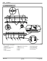
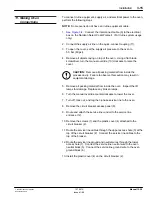
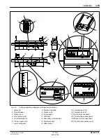
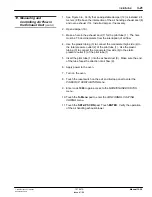
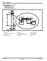
1. See Figure 3-6. Verify that an adjustable damper (12) is installed 2.4
meters (8 ft) above the intersection of the air handing exhaust duct (8)
and oven exhaust (10). Install a damper, if necessary.
2. Open damper (10).
3. Make a hole in the exhaust duct (7) for the pitot tube (1). The hole
must be 7.5 duct diameters from the interruption of air flow.
4. Use the plastic tubing (3) to connect the manometer high side (4) to
the total pressure outlet (2) of the pitot tube (1). Use the plastic
tubing (3) to connect the manometer low side (6) to the static
pressure outlet (7) of the pitot tube (1).
5. Insert the pitot tube (1) into the exhaust duct (8). Make sure the end
of the tube faces the direction of air flow (9).
6. Apply power to the oven.
7. Turn on the oven.
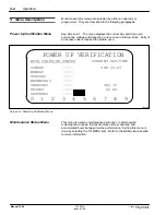
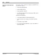
8. Touch the reset switch on the exit end E-stop panel to enter the
POWER UP VERIFICATION menu.
9. Enter code 1960 to gain access to the
MAINTENANCE STATUS
menu.
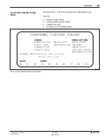
10. Touch the To Menu pad to enter the
CONFORMAL COATING
CURING menu.
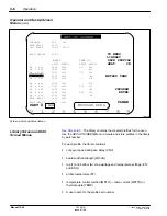
11. Touch the SET-UP SCRN pad. Touch ENTER. Verify the operation
of the air handling exhaust blower.
13. Measuring and
Controlling Air Flow in
the Exhaust Duct
(contd.)
Summary of Contents for 107 041A
Page 1: ...Select Cure 100 Inch IR Oven Part 107 041A NORDSON CORPORATION D AMHERST OHIO D USA ...
Page 9: ...E 1995 Nordson Corporation All rights reserved Issued 11 95 12 28s1 Section 1 Safety ...
Page 10: ...Safety 1 0 E 1995 Nordson Corporation All rights reserved Issued 11 95 12 28s1 ...
Page 148: ...Parts 7 0 E 1996 Nordson Corporation All rights reserved 107 041A Issued 1 96 Manual 12 28 ...

