4 Commissioning
BU 0135 en-4118
79
BUS-OUT Function (P434 [-01 … -02])
Status
Status
Bit 1 Bit 0
Bit 0
Fault (status bit 0)
0
0
Error active
Bit 1
Operation (status bit 1)
0
1
Standby (motor stationary)
Bit 2
1)
Status of initiator 1 (DIN3 / C1)
1
0
Warning (but motor running)
Bit 3
1)
Status of initiator 2 (DIN4 / C2)
1
1
Run (motor running without warning)
1)
Bits 2 and 3 are directly coupled to digital inputs 3 and
4.
Parallel actuation via the BUS and the digital inputs (C1, C2) is possible. The relevant inputs are dealt
with more or less as normal digital inputs. If a changeover between manual and automatic is going to
take place, it must be ensured that no enable via the normal digital inputs takes place in automatic
mode. This could be implemented e.g. with a three-position key switch. Position 1: "Manual left"
Position 2: "Automatic" Position 3: "Manual right".
If an enable is present via one of the two "normal" digital inputs, the control bits from the bus system
are ignored. An exception is the control bit "Acknowledge fault". This function is always possible in
parallel, regardless of the control hierarchy. The bus master can therefore only take over control if no
actuation via a digital input takes place. If "Enable left" and "Enable right" are set simultaneously, the
enable is removed and the motor stops without a deceleration ramp (block voltage).
4.4.3.4 Addressing
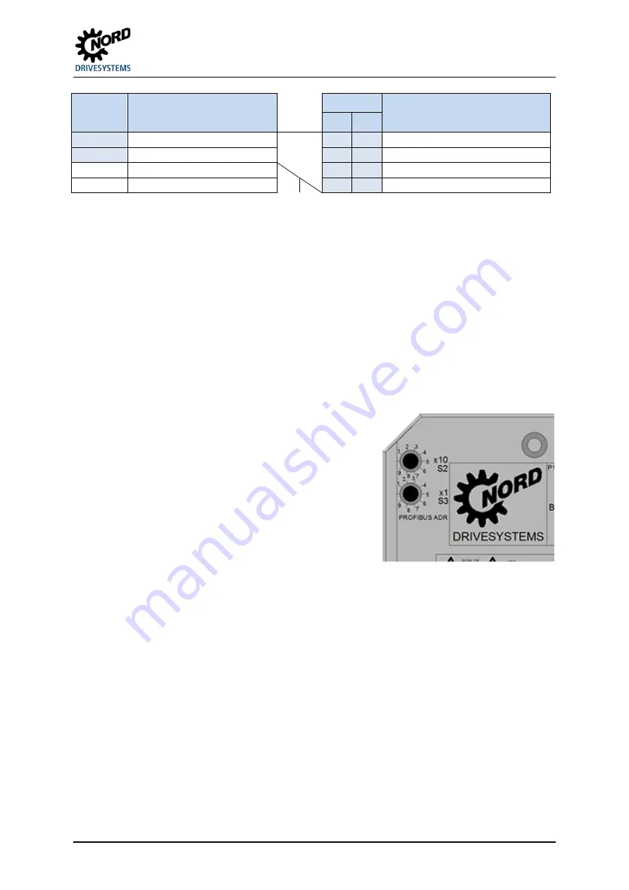
The motor switch is addressed via two decimal rotary
coding switches.
Switch "x1 S3"
• Setting of decimal number range from 0 to 9
Switch "x10 S2"
• Setting of 10's location of the address. The setting
range 0 to 9 is linked with a factor of 10.
Example
Switch S2 = 4 (
4
x)
Switch S3 = 2 (
x
2
)
Resulting PROFIBUS address =
42
The PROFIBUS address of the motor starter can be set within a range of 1 to 79 and 81 to 99 with the
rotary coding switches.
If
addresses 0 or 80
are set, the motor starter interprets these values as an address of 126.
Communication
is
not possible
in this case.
The address is read in directly after switching on the 24 V supply of the motor starter.
An
address change
only comes into affect on the voltage supply of the device
after
switching the
24 V DC on again
!
Summary of Contents for NORDAC START Series
Page 1: ...BU 0135 en NORDAC START SK 135E SK 175E Users Manual for Motor Starters...
Page 4: ...NORDAC START SK 135E SK 175E Users Manual for Motor Starters 4 BU 0135 en 4118...
Page 111: ...8 Additional information BU 0135 en 4118 111 8 1 4 EU Declaration of Conformity...
Page 119: ...Key word index BU 0135 en 4118 119...
Page 120: ...6071302 4118...


