TPC6000
‐
6151
User
Manual
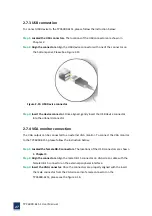
26
Figure
2
‐
13:
LAN
connection
Step
3:
Insert
the
LAN
cable
RJ
‐
45
connector.
Once
aligned,
gently
insert
the
LAN
cable
RJ
‐
45
connector
into
the
onboard
RJ
‐
45
port.
2.7.2
Serial
device
connection
The
serial
device
connectors
are
for
connecting
serial
devices
to
the
TPC6000
‐
6151.
Follow
the
steps
below
to
connect
a
serial
device
to
the
TPC6000
‐
6151
panel
PC.
Step
1:
Locate
the
DB
‐
9
connector
.
The
location
of
the
DB
‐
9
connector
is
shown
in
chapter
2.
Step
2:
Insert
the
serial
connector.
Insert
the
DB
‐
9
connector
of
a
serial
device
into
the
DB
‐
9
connector
on
bottom
panel.
Please
see
Figure
2
‐
14.
Figure
2
‐
14:
Serial
device
connector
Step
3:
Secure
the
connector.
Secure
the
serial
device
connector
to
the
external
interface
by
tightening
the
two
retention
screws
on
either
side
of
the
connector.
Summary of Contents for TPC6000-6151
Page 1: ...TPC6000 6151 User Manual 1 User Manual Ver1 4 TPC6000 6151 Industrial Panel PC...
Page 8: ...TPC6000 6151 User Manual 8 Chapter 1 OVERVIEW...
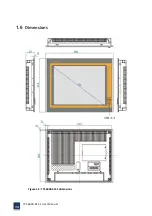
Page 14: ...TPC6000 6151 User Manual 14 1 6 Dimensions Figure 1 5 TPC6000 6151 dimensions...
Page 15: ...TPC6000 6151 User Manual 15 Chapter 2 INSTALLATIONS...
Page 35: ...TPC6000 6151 User Manual 35 Press YES to agree the License agreement then go to the next step...
Page 41: ...TPC6000 6151 User Manual 41 Press YES to agree the License agreement then go to the next step...
Page 43: ...TPC6000 6151 User Manual 43 Press YES to continue...
Page 46: ...TPC6000 6151 User Manual 46 Press NEXT to continue...
Page 48: ...TPC6000 6151 User Manual 48...
Page 51: ...TPC6000 6151 User Manual 51 Press NEXT to continue Press INSTALL to continue...
Page 53: ...TPC6000 6151 User Manual 53 Chapter 3 BIOS Setup...
Page 62: ...TPC6000 6151 User Manual 62 Figure 3 3 5 USB Configuration 3 3 6 Super I O Configuration...
Page 64: ...TPC6000 6151 User Manual 64 3 3 7 PC Health Status Figure 3 3 7 PC Health status...
Page 65: ...TPC6000 6151 User Manual 65 3 3 8 PPM Configuration Figure 3 3 8 PPM Configuration EIST...
Page 71: ...TPC6000 6151 User Manual 71...
Page 72: ...TPC6000 6151 User Manual 72...
Page 75: ...TPC6000 6151 User Manual 75 3 5 4 BOOT Configuration...
Page 76: ...TPC6000 6151 User Manual 76 3 6 Exit Option Figure 3 6 Exit Option...
Page 78: ...TPC6000 6151 User Manual 78 Chapter 4 System Maintenance...
Page 80: ...TPC6000 6151 User Manual 80 Figure 4 1 Back cover retention screws...
Page 81: ...TPC6000 6151 User Manual 81 A Safety Precautions...
Page 85: ...TPC6000 6151 User Manual 85 B ALC662 Digital Microphone Configuration...
Page 90: ...TPC6000 6151 User Manual 90 C Watchdog Timer...
Page 93: ...TPC6000 6151 User Manual 93 D Hazardous Materials Disclosure...
Page 96: ...TPC6000 6151 User Manual 96 Chapter 5 Appendix A...

