TPC6000
‐
6151
User
Manual
10
4
x
RS
‐
232
/
RS485
serial
port
(selectable),
with
magnetic
‐
coupling
isolation
and
surge
protection;
DC
9~30V
wide
voltage
power
supply
with
over
voltage,
over
current
and
power
reverse
protection;
Interfaces:
VGA
/
2
x
GLAN
/
5
x
USB
/
4
x
COM
/
LPT
/
AUDIO;
1.3
External
Overview
The
TPC6000
‐
6151
consists
of
a
screen
and
a
rear
panel
that
covers
the
back,
side
and
top.
The
rear
panel
contains
a
smaller
access
panel,
all
the
cable
connections
and
mounting
holes.
1.3.1
Front
panel
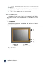
The
front
side
of
the
TPC6000
‐
6151
is
flat
panel
LCD
screen
surrounded
by
an
aluminum
magnesium
alloy
die
‐
cast
frame.
Figure
1
‐
2:
Front
panel
Summary of Contents for TPC6000-6151
Page 1: ...TPC6000 6151 User Manual 1 User Manual Ver1 4 TPC6000 6151 Industrial Panel PC...
Page 8: ...TPC6000 6151 User Manual 8 Chapter 1 OVERVIEW...
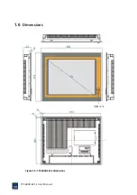
Page 14: ...TPC6000 6151 User Manual 14 1 6 Dimensions Figure 1 5 TPC6000 6151 dimensions...
Page 15: ...TPC6000 6151 User Manual 15 Chapter 2 INSTALLATIONS...
Page 35: ...TPC6000 6151 User Manual 35 Press YES to agree the License agreement then go to the next step...
Page 41: ...TPC6000 6151 User Manual 41 Press YES to agree the License agreement then go to the next step...
Page 43: ...TPC6000 6151 User Manual 43 Press YES to continue...
Page 46: ...TPC6000 6151 User Manual 46 Press NEXT to continue...
Page 48: ...TPC6000 6151 User Manual 48...
Page 51: ...TPC6000 6151 User Manual 51 Press NEXT to continue Press INSTALL to continue...
Page 53: ...TPC6000 6151 User Manual 53 Chapter 3 BIOS Setup...
Page 62: ...TPC6000 6151 User Manual 62 Figure 3 3 5 USB Configuration 3 3 6 Super I O Configuration...
Page 64: ...TPC6000 6151 User Manual 64 3 3 7 PC Health Status Figure 3 3 7 PC Health status...
Page 65: ...TPC6000 6151 User Manual 65 3 3 8 PPM Configuration Figure 3 3 8 PPM Configuration EIST...
Page 71: ...TPC6000 6151 User Manual 71...
Page 72: ...TPC6000 6151 User Manual 72...
Page 75: ...TPC6000 6151 User Manual 75 3 5 4 BOOT Configuration...
Page 76: ...TPC6000 6151 User Manual 76 3 6 Exit Option Figure 3 6 Exit Option...
Page 78: ...TPC6000 6151 User Manual 78 Chapter 4 System Maintenance...
Page 80: ...TPC6000 6151 User Manual 80 Figure 4 1 Back cover retention screws...
Page 81: ...TPC6000 6151 User Manual 81 A Safety Precautions...
Page 85: ...TPC6000 6151 User Manual 85 B ALC662 Digital Microphone Configuration...
Page 90: ...TPC6000 6151 User Manual 90 C Watchdog Timer...
Page 93: ...TPC6000 6151 User Manual 93 D Hazardous Materials Disclosure...
Page 96: ...TPC6000 6151 User Manual 96 Chapter 5 Appendix A...


