TPC6000
‐
6151
User
Manual
27
2.7.3
USB
connection
To
connect
USB
device
to
the
TPC6000
‐
6151,
please
follow
the
instruction
below:
Step
1:
Located
the
USB
connectors.
The
locations
of
the
USB
connectors
are
shown
in
Chapter
2.
Step
2:
Align
the
connectors.
Align
the
USB
device
connector
with
one
of
the
connector
on
the
bottom
panel.
Please
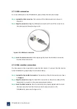
See
Figure
2
‐
15
Figure
2
‐
15:
USB
Device
connector
Step
3:
Insert
the
device
connector.
Once
aligned,
gently
insert
the
USB
device
connector
into
the
onboard
connector.
2.7.4
VGA
monitor
connection
The
VGA
output
can
be
connected
to
an
external
VGA
monitor.
To
connect
the
VGA
monitor
to
the
TPC6000
‐
6151,
please
follow
the
instruction
below:
Step
1:
Located
the
female
DB
‐
9
connectors.
The
locations
of
the
USB
connectors
are
shown
in
Chapter
3
.
Step
2:
Align
the
connectors.
Align
the
male
DB
‐
15
connector
on
VGA
screen
cable
with
the
female
DB
‐
15
connector
on
the
external
peripheral
interface.
Step
3:
Insert
the
VGA
connector.
Once
the
connectors
are
properly
aligned
with
the
insert
the
male
connector
from
the
VGA
screen
into
female
connector
on
the
TPC6000
‐
6151,
please
see
the
figure
2
‐
16:
Summary of Contents for TPC6000-6151
Page 1: ...TPC6000 6151 User Manual 1 User Manual Ver1 4 TPC6000 6151 Industrial Panel PC...
Page 8: ...TPC6000 6151 User Manual 8 Chapter 1 OVERVIEW...
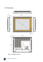
Page 14: ...TPC6000 6151 User Manual 14 1 6 Dimensions Figure 1 5 TPC6000 6151 dimensions...
Page 15: ...TPC6000 6151 User Manual 15 Chapter 2 INSTALLATIONS...
Page 35: ...TPC6000 6151 User Manual 35 Press YES to agree the License agreement then go to the next step...
Page 41: ...TPC6000 6151 User Manual 41 Press YES to agree the License agreement then go to the next step...
Page 43: ...TPC6000 6151 User Manual 43 Press YES to continue...
Page 46: ...TPC6000 6151 User Manual 46 Press NEXT to continue...
Page 48: ...TPC6000 6151 User Manual 48...
Page 51: ...TPC6000 6151 User Manual 51 Press NEXT to continue Press INSTALL to continue...
Page 53: ...TPC6000 6151 User Manual 53 Chapter 3 BIOS Setup...
Page 62: ...TPC6000 6151 User Manual 62 Figure 3 3 5 USB Configuration 3 3 6 Super I O Configuration...
Page 64: ...TPC6000 6151 User Manual 64 3 3 7 PC Health Status Figure 3 3 7 PC Health status...
Page 65: ...TPC6000 6151 User Manual 65 3 3 8 PPM Configuration Figure 3 3 8 PPM Configuration EIST...
Page 71: ...TPC6000 6151 User Manual 71...
Page 72: ...TPC6000 6151 User Manual 72...
Page 75: ...TPC6000 6151 User Manual 75 3 5 4 BOOT Configuration...
Page 76: ...TPC6000 6151 User Manual 76 3 6 Exit Option Figure 3 6 Exit Option...
Page 78: ...TPC6000 6151 User Manual 78 Chapter 4 System Maintenance...
Page 80: ...TPC6000 6151 User Manual 80 Figure 4 1 Back cover retention screws...
Page 81: ...TPC6000 6151 User Manual 81 A Safety Precautions...
Page 85: ...TPC6000 6151 User Manual 85 B ALC662 Digital Microphone Configuration...
Page 90: ...TPC6000 6151 User Manual 90 C Watchdog Timer...
Page 93: ...TPC6000 6151 User Manual 93 D Hazardous Materials Disclosure...
Page 96: ...TPC6000 6151 User Manual 96 Chapter 5 Appendix A...


