TPC6000
‐
6151
User
Manual
24
enough
for
the
rear
panel
of
the
flat
panel
PC
to
fit
through.
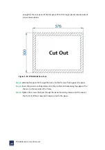
Recommended
cutout
size
as
shown
below:
Figure
2
‐
10:
TPC6000
‐
6151
cut
out.
Step
3:
Slide
the
flat
panel
PC
through
the
hole
until
the
frame
is
flush
against
the
panel.
Step
4:
Insert
the
panel
mounting
clamps
into
the
pre
‐
formed
holes
along
the
edges
of
the
chassis,
on
the
two
side
of
the
frame.
Step
5:
Tighten
the
screws
that
pass
through
the
panel
mounting
clamps
until
the
caps
at
the
front
of
all
the
screws
are
firmly
secured
to
the
panel.
Summary of Contents for TPC6000-6151
Page 1: ...TPC6000 6151 User Manual 1 User Manual Ver1 4 TPC6000 6151 Industrial Panel PC...
Page 8: ...TPC6000 6151 User Manual 8 Chapter 1 OVERVIEW...
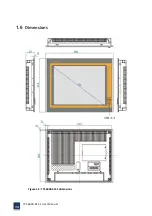
Page 14: ...TPC6000 6151 User Manual 14 1 6 Dimensions Figure 1 5 TPC6000 6151 dimensions...
Page 15: ...TPC6000 6151 User Manual 15 Chapter 2 INSTALLATIONS...
Page 35: ...TPC6000 6151 User Manual 35 Press YES to agree the License agreement then go to the next step...
Page 41: ...TPC6000 6151 User Manual 41 Press YES to agree the License agreement then go to the next step...
Page 43: ...TPC6000 6151 User Manual 43 Press YES to continue...
Page 46: ...TPC6000 6151 User Manual 46 Press NEXT to continue...
Page 48: ...TPC6000 6151 User Manual 48...
Page 51: ...TPC6000 6151 User Manual 51 Press NEXT to continue Press INSTALL to continue...
Page 53: ...TPC6000 6151 User Manual 53 Chapter 3 BIOS Setup...
Page 62: ...TPC6000 6151 User Manual 62 Figure 3 3 5 USB Configuration 3 3 6 Super I O Configuration...
Page 64: ...TPC6000 6151 User Manual 64 3 3 7 PC Health Status Figure 3 3 7 PC Health status...
Page 65: ...TPC6000 6151 User Manual 65 3 3 8 PPM Configuration Figure 3 3 8 PPM Configuration EIST...
Page 71: ...TPC6000 6151 User Manual 71...
Page 72: ...TPC6000 6151 User Manual 72...
Page 75: ...TPC6000 6151 User Manual 75 3 5 4 BOOT Configuration...
Page 76: ...TPC6000 6151 User Manual 76 3 6 Exit Option Figure 3 6 Exit Option...
Page 78: ...TPC6000 6151 User Manual 78 Chapter 4 System Maintenance...
Page 80: ...TPC6000 6151 User Manual 80 Figure 4 1 Back cover retention screws...
Page 81: ...TPC6000 6151 User Manual 81 A Safety Precautions...
Page 85: ...TPC6000 6151 User Manual 85 B ALC662 Digital Microphone Configuration...
Page 90: ...TPC6000 6151 User Manual 90 C Watchdog Timer...
Page 93: ...TPC6000 6151 User Manual 93 D Hazardous Materials Disclosure...
Page 96: ...TPC6000 6151 User Manual 96 Chapter 5 Appendix A...

