

www.nitronic.ch
-
41 -
Nitronic AG
Mattenstrasse 11
CH – 2555 Bruegg
Tel.
+41 32 373 7070
Switzerland
Fax
+41 32 373 70
75
•
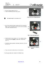
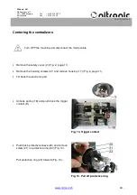
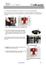
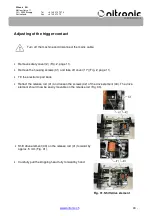
Rotate the threaded spindle (28) until the distance between the cutting edges of blades (12) is 7
mm (Fig. 32).
•
Pull release contact (9) forward until the distance between trig-
ger contact (9) and the cutting edges of blades (12) is 0.5 mm
(Fig. 32).
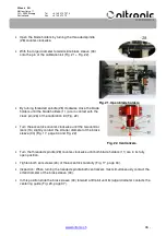
•
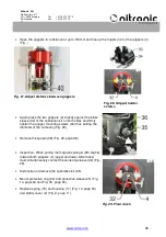
Carefully tighten the screws (42) of the drive element (43) (Fig.
31).
•
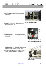
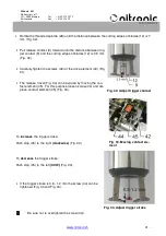
The release travel (Fig. 34) can be varied by moving the con-
tact element (45). For this purpose loosen screw (44) and dis-
place contact element (45) (Fig. 33).
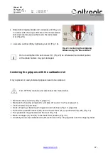
To
increase
the trigger stroke:
Push stop (45) to the right
(clockwise)
(Fig. 33).
To
decrease
the trigger stroke:
Push stop (45) to the left
(CCW)
(Fig. 33).
•
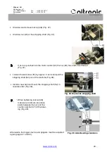
If the trigger stroke is 0.8 - 1.2 mm the screw (44) can be
tightened (Fig. 33 and Fig. 34).
Be sure not to overtighten the screw (44)!
Fig. 32. Adjust trigger contact
Fig. 33. Moving contact ele-
ment
Fig. 34. Adjust trigger stroke