www.nitronic.ch
-
35 -
Nitronic AG
Mattenstrasse 11
CH – 2555 Bruegg
Tel.
+41 32 373 7070
Switzerland
Fax
+41 32 373 70
75
•
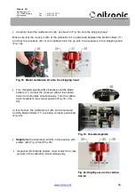
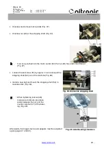
Carefully install the calibration kit (25, as shown in Fig. 18) onto the stripping head.
Make sure that the cross pin (26) of the calibration kit is positioned between the blade holders (11)
and that the recesses (27) of the calibration kit line up with the eccentrics in the stripping head
(Fig. 18).
•
Turn threaded spindle (28) clockwise until the blade
holders (11) contact the cross pin (26) of the calibra-
tion kit on both sides simultaneously. Turn the calibra-
tion kit slightly to the correct position (Fig. 19 + Fig.
20).
In this manner, the calibration kit (25) can be centered
and the blade holders (11) are being correctly positioned
(Fig. 20).
•
Slightly fix
the calibration kit (25) in this position with
screws (29)
(Fig. 20 and Fig. 18).
•
Inspection: Both blade holders must contact the cross
pin (26) of the calibration kit simultaneously.
Fig. 18. Mount calibration kit onto the stripping head
Fig. 19. Threaded spindle
Fig. 20. Slightly secure the calibra-
tion kit

