143
Service Manual – SW5500, FLOORTEC R 985
24 - Electrical System
Alternator (Diesel Version)
Removal
1 Remove the engine/alternator assembly (see
in the Engine System - Diesel chapter)
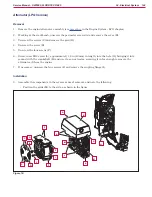
2 Working at the workbench, unscrew the perimeter screws (A, ) and remove the cover (B)
3 Unscrew the screws (C) and remove the grid (D)
4 Unscrew the screw (E)
5 Unscrew the four screws (F)
6 Screw in an M12 screw (L), approximately 1,6 in (40 mm) in length, into the hole (G), bringing it into
contact with the crankshaft (H) and use it as an extractor, screwing it in far enough to remove the
alternator (I) from the engine
7
If necessary, unscrew the four screws (J) and remove the coupling flange (I).
Installation
8 Assemble the components in the reverse order of removal, and note the following:
◦ Position the grids (M) to the side, as shown in the figure.
Figure 17:
A
H
M
K
M
J
J
F
I
F
F
G
E
C
C
D
A
B
A
L

