


267
Service Manual – SW5500, FLOORTEC R 985
52 - Hopper System
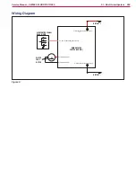
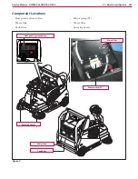
Functional Description
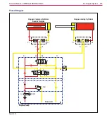
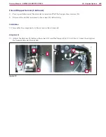
The hopper lifting and dumping system is operated by two hydraulic cylinders driven by an hopper pump
(M3) with integrated hydraulic unit
The hopper pump (M3) is powered by the Main Machine Controller (EB1)
Activation of various solenoid valves allows the hopper pump (M3) to move the two hydraulic cylinders in the
required direction, according to the following table:
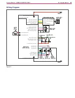
ACTIVATION OF OUTPUTS FOR HOPPER MOVEMENTS
Command
Button
HOPPER PUMP
(M3)
RAISING VALVE
(EV1)
LOWERING VALVE
(EV2)
DUMPING VALVE
(EV3)
Raise
X
X
Lower
X
X
Dumping
X
X
Return to horizontal
position
X
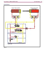
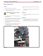
When the hopper comes out of its rest position, the hopper closed sensor (S1, light sensor on) provides its
signal to the Main Machine Controller (EB1) in order to obtain the following automatic functions: reduction
of machine maximum speed, sounding of the buzzer (BZ, on the Main Machine Controller), displaying the
hopper lifting icon on the display, switching off the vacuum system motor (M1) and the broom motors (M4,
M5, M6)
When the hopper reaches a height sufficient to activate the hopper lifted sensor (S2, light sensor on),
rotation of the hopper can be activated with the dumping button to empty the hopper, and then the return
button can be used to return the hopper to the horizontal position
When the hopper dumping sensor (S3) detects that the hopper is not in the horizontal position, activation of
the hopper lowering button is disabled
When the hopper is not in the horizontal position, the hopper dumping sensor (S3, light sensor off) disables
the activation of the hopper lowering button
SENSORS HOPPER WORK
Sensor
Light built-in
sensor
Sensor
output
Effect
S1
OFF
0V
-
ON
24V
- Low gear speed - No vacuum - No brooms rotation - Buzzer ON
S2
OFF
0V
- No hopper dumping (inhibited dumping button)
ON
24V
-
S3
OFF
0V
- No hopper lowering (inhibited lower button)
ON
24V
-