101
Service Manual – SW5500, FLOORTEC R 985
20 - Wheel System, Traction
Driving Wheel Motor Current Draw Check (continues)
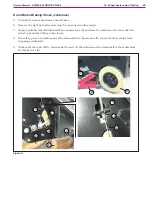
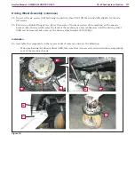
8 For safety purposes, to prevent accidental lowering of the machine, apply two suitable spacers under the
right (I) and left (J) side brackets
9 Working on the drive board (M), apply the ammeter clamp (K) to the drive motor electrical cable (L)
10 Start the machine with the ignition key
11 With the help of an assistant, carefully seat on the driver’s seat to activate the microswitch, then turn
on the drive system at the maximum speed and check that the driving wheel amperage is within 15 and
25A at 24Vac
Stop the drive system
Turn the ignition key to “0”
Remove the ammeter clamp (K)
If the amperage is higher, perform the following procedures to detect and correct it:
◦
Check that there is no dust or debris (ropes, cables, etc ) on the driving wheel, that can prevent it
from turning
◦
If necessary, disassemble the drive system motor (see
in the relevant paragraph), and
check the condition of all its components
If the above-mentioned procedures do not lead to a correct amperage, the drive system motor must be
replaced (see
Reassembly
12 Perform steps 3 to 7 in the reverse order
Figure 6:
I
K
L
J
M


