80
Service Manual – SW5500, FLOORTEC R 985
05 - Control System
Shop Measurements - Display Controller (EB3) (continues)
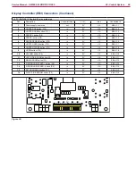
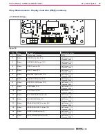
J2: FCI DUFLEX type
J2
Figure 54:
PIN
Color
Description
Measured/Condition
1
Ribbon
Power supply - common
0.007V
2
Ribbon
HOPPER UP button (P10)
Not Pressed - 3.1V
Presssed - 0.009V
3
Ribbon
HOPPER DOWN button (P11)
Not Pressed - 3.1V
Presssed - 0.009V
4
Ribbon
SPEED + button (P8)
Not Pressed - 3.1V
Presssed - 0.009V
5
Ribbon
SPEED - button (P9)
Not Pressed - 3.1V
Presssed - 0.009V
6
Ribbon
REVERSE GEAR button (P15)
Not Pressed - 3.1V
Presssed - 0.009V
7
Ribbon
HOPPER OPEN button (P12)
Not Pressed - 3.1V
Presssed - 0.009V
8
Ribbon
HOPPER CLOSE button (P13)
Not Pressed - 3.1V
Presssed - 0.009V
9
Ribbon
HORN button (P14)
Not Pressed - 3.1V
Presssed - 0.009V
10
Ribbon
VACUUM button (P6)
Not Pressed - 3.1V
Presssed - 0.009V
11
Ribbon
LEFT SIDE BROOM button (P3)
Not Pressed - 3.1V
Presssed - 0.009V
12
Ribbon
MAIN BROOM button (P1)
Not Pressed - 3.1V
Presssed - 0.009V
13
Ribbon
SIDE BROOM SPEED + button (P4)
Not Pressed - 3.1V
Presssed - 0.009V
14
Ribbon
SIDE BROOM SPEED - button (P5)
Not Pressed - 3.1V
Presssed - 0.009V
15
Ribbon
FILTER SHAKER button (P7)
Not Pressed - 3.1V
Presssed - 0.009V
16
Ribbon
RIGHT SIDE BROOM button (P2)
Not Pressed - 3.1V
Presssed - 0.009V


