127
Service Manual – SW5500, FLOORTEC R 985
24 - Electrical System
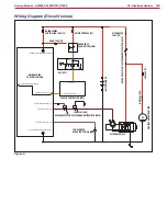
Functional Description - Diesel, LPG Version
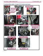
The electrical system of Diesel and LPG versions is
substantially equal to that of the battery versions,
the difference is that the 24V battery pack is
replaced by one with lower capacity (2 x 12Vdc
starter batteries) kept charged by a three-phase
alternator and a three-phase power bridge rectifier.
Between the output of the bridge rectifier and the
battery pack is the relay (ES10) contact and the
charging system fuse (F4)
The relay (ES10) separates the output of the rectifier
from the batteries when the engine is running with
all services switched off for over 10 sec or when the
battery voltage reaches the limit value of 32V
The Diesed and LPG engine are started via the
starter motor (MST) when the key switch (KEY) is
turned to position II
The Main Machine Controller (EB1) continuously
checks the alternator output voltage (D1, alternator
input J1 14) to determine if the engine is on or off
With off engine the sweeping and vacuum functions
are inhibited
Only on LPG version
The electronic engine speed regulation system
(EB6) reduces the engine speed from 3,000 rpm to
2,300 rpm when the relay (ES10) disconnects the
rectifier output from the batteries. Commands to
the electronic system of the engine are provided
by opening the contacts of the relay (ES4) which is
driven by the Main Machine Controller (EB1)
(NB: the reduction in engine speed may not be
immediate as the engine electronic system takes
other parameters into account such as engine
temperature and carburation when deciding
whether to reduce the set speed or not, even if the
corresponding input is open)
The engine fuel supply system is fitted with a safety
solenoid valve (EV4) which allows LPG to flow to the
engine only when powered
The solenoid valve (EV4) is powered when the key
switch (KEY) is in position II, and for the first 10
seconds of operation when it is in position I After
these 10 seconds have passed, if the engine has
not been started power is cut to the solenoid valve;
otherwise, it remains active as long as the engine is
running
The solenoid valve is managed by the Main Machine
Controller (EB1), via output J2 6 The Main Machine
Controller (EB1) checks the status of the engine
via input J1 14 connected to the secondary bridge
rectifier (D1).
The entire electrical and electronic system of the
engine (including the starter motor) runs on 12V,
taken from one of the machine’s two 12V batteries
The engine is equipped with an internal alternator
which restores the energy taken from the 12V
battery on starting
Only on Diesel version
The engine fuel supply system is fitted with a safety
solenoid valve (EV4) and a fuel pump (P2) which
allow diesel to flow to the engine only when powered.
The solenoid valve (EV4) and the pump (P2) are
powered when the key switch (KEY) is in position II,
and for the first 10 seconds of operation when it is
in position I After these 10 seconds have passed, if
the engine has not been started power is cut to them;
otherwise, they remain active as long as the engine
is running
The solenoid valve and the pump are managed by
the Main Machine Controller (EB1) via output J2 6
which activates relay (ES7) The Main Machine
Controller (EB1) checks the status of the engine
via input J1 14 connected to the secondary bridge
rectifier (D1).
The solenoid valve (EV4) and the pump (P2) run at
approx 12V, reducing the battery voltage (24V) via
the resistor (R4)


