www.usmotors.com
28
ID300/302 Integrated Motor Drive |
Connections
4.6 Control Terminals
• The control circuits are isolated from the power circuits by single insulation only. The installer must
ensure that the external control circuits are insulated from human contact by at least one layer of
insulation (supplementary insulation) rated for use at the AC supply voltage.
•
If the control circuits are to be connected to other circuits classified as Safety Extra Low Voltage
(SELV) (e.g., to a personal computer), an additional isolating barrier must be included in order to
maintain the SELV classification.
• If any of the digital inputs (including the drive enable or STO inputs) are connected in parallel with
an inductive load (i.e., contactor or motor brake), then suitable suppression (i.e., diode or varistor)
should be used on the coil of the load. If no suppression is used, then over voltage spikes can
cause damage to the ID300/302digital inputs and outputs.
• When the ID300/302 is controlled remotely, avoid routing of power cables and control cables in
close proximity with each other.
• Ensure that the logic polarity is correct for the control circuit to be used. Incorrect logic polarity
could cause the motor to be started unexpectedly. Positive logic is required for the ID300/302.
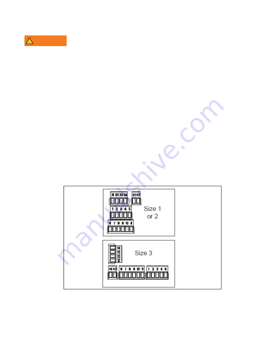
• To avoid putting pressure on the PCB card, ensure that the terminal blocks have been removed
from their fixed holder (unplugged) before making any connections.
The ID300/302 is delivered with the ‘STANDARD Keypad’ default configuration.
Control Terminal Blocks
WARNING
!


