background image

User’s Manual 


79 

Inside The Range:


The value of transaction within a certain range will be marked as an exception. 
The range needs to be configured through the following sub-settings <Value> 
and <Value (Upper Limit)>.   


Outside the Range: 

The value of transaction outside a certain range will be marked as an 
exception. The range need to be configured through the following 
sub-settings <Value> and <Value (Upper Limit)>. 
 

NOTE:

 Transactions will only be marked as exceptions in the text 

database after “Exception String” and “By Numerals” are set AND 
“Trigger” is <ON>. The data that has been stored before won't be 
marked as exceptions.   


< Input Setup > 

This item is used to choose the connection method between your Text Device and the DVR.   
Also some relative settings of the connection method can be configured. 
 

Input Setup 

1. Port Selection 
2. Input Source 
3. Camera Selection 
4. Text Filter 
5.  Manual Filter Setup 
6. Input Process 
7.  Text Baud Rate 
8. Text Bits 
9. Text Stop 
10. Text Parity 

Serial Port 

Direct Connected 

ASCII 


Canonical 

9600 


None 


„


Port Selection 

It is essential to select a port for either the POS/cash register or modem when 
the text function is set on. Meanwhile, also check whether the device is 
connected to the port selected. 
 

Port Selection 

1. Serial Port  
2. USB Port-Front 
3. USB Port-Rear Top 
4.  USB Port-Rear Bottom 

Text 

None 
None 
None 


Summary of Contents for Premium H.264 DVR

Page 1: ...Ness Ultimate Premium H 264 DVR OSD Setup Manual REV1 1 Sep11 ...

Page 2: ... Address 2 13 Software Upgrade via Local Device 13 Software Upgrade via Internet 14 Language 14 Date Time 14 Date Time 14 Time Zone 15 Date Time Display 15 Date Display Mode 15 Time Display Mode 16 Date Time Order 16 Daylight Saving Time Setup 16 Daylight Saving Time 16 DST Start End 16 DST Bias 16 Network Time Protocol Setup 17 Unit Name 17 Show Unit Name 18 User Management 18 Password Protection...

Page 3: ...Network Name ESSID 25 Network Authentication 26 Data Encryption 26 Data Encryption Level 27 Key Index 27 Enter Network Key 27 Network Setting 28 Connect 28 Modem Setup 28 Dial in Setup 28 Dial in Service 29 Dial in Account 29 Dial in Password 30 Server IP 30 Client IP 30 Dial in Idle Time 31 Dial in Max Time 31 Dial out Setup 31 Dial out DHCP 32 Dial out IP 32 Dial out Netmask 32 Dial out Gateway ...

Page 4: ...TP Password 37 DDNS Setup 37 Enable DDNS 37 Host Name 37 DDNS Port 38 Submit Update 38 ezDDNS 39 UPnP 39 UPnP 39 UPnP NAT Traversal 39 RS485 Setup 40 Unit ID 40 Baud Rate 40 Bits 40 Stop 40 Parity 40 Audio Output Key Beep 40 Audio Output 41 Key Beep 41 Monitor Setup 42 Show Camera Title 42 Title Position 42 Main Monitor Output Select 43 Simultaneous Output 43 Monitor Brightness 43 Monitor Contrast...

Page 5: ... Frequency 45 Show Color Bar 45 Camera Setup 46 Analog Camera 46 Analog Camera Select 46 Dome Protocol 46 Dome ID 46 Camera Title 47 Covert 47 Termination 48 Brightness 48 Contrast 48 Saturation 48 Hue 48 Audio Association 48 Record Setup 54 Record Mode Setup 54 ...

Page 6: ...Event Active 58 ezRecord Setup 58 Data Lifetime 59 Pre Alarm Recording 59 Circular Recording 59 Audio Recording 60 Purge Data 60 Purge All Data 60 Purge All Event Data 60 Purge Event Before 60 Start To Purge 60 Sequence Setup 61 Main Call Monitor Dwell 61 Main Call Monitor Schedule 61 Event Setup 62 Internal Buzzer 62 Event Icon 62 Email Notice 62 Email Attachment 63 SMS Setup 63 SMS Notice 63 PIN...

Page 7: ...rea Setup 67 Sensitivity 67 Area Threshold 67 Alarm In 68 Alarm Out 68 Database Setup 69 Total Free Size of HDD 69 Avail Rec Time 69 Internal External Disks 69 NAS Devices 70 Configuration 71 Load Factory Default 71 Import Configuration 71 Export Configuration 72 Copy Destination 72 Configuration Name 72 Begin Export 72 Video Export 73 Select Device 74 Select Channel 74 From To Time 75 Select Even...

Page 8: ...Selection 80 Text Filter 80 Manual Filter Setup 81 Input Process 81 Text Baud Rate 81 Text Bit 81 Text Stop 81 Text Parity 81 Shutdown 82 Power Off 82 Reboot 82 Appendix A Record Duration 83 Appendix B Dial up Connections via Modem 85 Establishing Dial in Connection 85 Establishing Dial out Connection 90 Appendix C DVR Player 95 Appendix D ezRecord Diagram Sample 100 Appendix E HDD COPY TOOL EXT2I...

Page 9: ...v w x y z 0 1 2 3 4 5 6 7 8 9 _ Backspace Delete Cancel OK The next step is to enter a corresponding password The preset password for admin is 1234 Password Verification ____________ Press Channel Keys To Enter Password 4 8 Digits Press Key To Delete NOTE It is strongly suggested to change the preset password to prevent unauthorized access to the unit An icon displayed at the center bottom of the ...

Page 10: ...e the cursor to previous or next fields UP DOWN are used to change the value in the selected field ENTER In OSD setup menu or selection interface press the key to make selection or save settings ESC Press to cancel or exit from certain OSD setup menu without saving any changes Key Usage in Virtual Keyboard A virtual keyboard shows when edit the settings such as camera title e mail address etc The ...

Page 11: ...ODE and LEFT RIGHT simultaneously to move the cursor to left right in the title entry field To delete previous character Select Backspace and press ENTER or press DOME To delete current character Select Delete and press ENTER To exit the virtual keyboard Select OK and press ENTER to save the settings and exit otherwise press ESC or select Cancel and press ENTER to exit without saving changes ...

Page 12: ...o view system information such as hardware and software version From the System Setup menu select System Version Info and press ENTER The following menu is displayed The first seven items are read only for users information only The items in this menu are described in the following subsections System Version Info Model Name Video System Hardware Software DSP MAC Address 1 MAC Address 2 Software Up...

Page 13: ...it then the available upgrade files will be listed in the menu To update the system select a file and use UP DOWN keys to choose Yes Press ENTER to confirm the selection and start the upgrade process The Premium H 264 DVR loads the software updates the system files and reboots automatically The upgrade may take several minutes to save the changes in the memory of the system After the unit is reboo...

Page 14: ...menu In System Setup menu select Date Time and press ENTER the Date Time menu displays as follows Date Time 1 Date 2 Time 3 Time Zone 4 Date Time Display 5 Date Display Mode 6 Time Display Mode 7 Date Time Order 8 Daylight Saving Time Setup 9 Network Time Protocol Setup 2008 02 21 PM10 39 26 OFF 1 Row Y M D 24 HR Date First NOTE The reset of date time settings only applies to new videos The date a...

Page 15: ...local time zone or the Network Time Protocol Setup will not be accessible Date Time Display Users are allowed to set the date time OSD displays in 1 or 2 rows Use the UP DOWN keys to change the setting Date Display Mode This function allows user to set the OSD display type of the date There are three options to select from Y M D M D Y or D M Y Y represents Year M represents Month and D represents ...

Page 16: ...e the function If the function is disabled the DST Start End time and DST Bias will be grayed out and cannot be accessed If this function is enabled the date time information will be shown on the screen with a DST icon when playing back recorded video or searching video in the event list S indicates summer time and W indicates wintertime DST Start End These items are used to set the daylight savin...

Page 17: ...rver is set select Manually Time Sync to sync the time The time sync can also be updated periodically Select Automatically Time Sync and choose a desired time interval to sync the time Unit Name Users are allowed to assign a name up to 11 characters to the Premium H 264 DVR Follow the steps to edit the unit name Select Unit Name from System Setup menu and press ENTER A virtual keyboard displays Un...

Page 18: ... accessing functions listed in Authority Setup menu or select OFF to allow free access Account Setup Setup customized username password and authority level in this menu Press Direction keys and ENTER to select items The username ID is case sensitive The authority level rank from level 1 8 and level 8 has highest authority Alternatively select Disable to stop using the account Account Setup Account...

Page 19: ...onitor Setup Camera Setup Record Setup Authority Level 4 Level 4 Level 4 Level 4 Level 4 Level 4 Level 4 Level 4 Level 4 NOTE The Menu Access cannot be set to Disable When the account does not have authority to access certain functions an error message will be displayed on the screen Load Default Setting This item is for restoring the default settings Select Yes to load default setting or select N...

Page 20: ...n broadband medium If None is selected then there is no need to set further LAN PPPoE WLAN settings Therefore the second item LAN Setup and third item Wireless Network Setup will be inaccessible LAN Setup The network related settings in the LAN Setup menu should be associated with the network service type If you select LAN for LAN Select then the 6th to 8th item will not be available Select LAN Se...

Page 21: ...nistrators or IT personnel for appropriate values for these settings IP The item is used to configure the IP Internet Protocol address of the unit The IP address is the identifier for your computer or device on a TCP IP LAN or WAN Please note that to set a static IP address DHCP must be set to OFF Netmask A netmask is a 32 bit mask used to divide an IP address into subnets and specify the networks...

Page 22: ...oots up slower than as usual The search of network continues until it times out PPPoE Account The item allows user to setup the PPPoE login username NOTE For accessing the PPPoE settings select PPPoE as the Network Type in Network Setup menu To setup the login username follow the steps Select PPPoE Account from LAN Setup menu and press ENTER A virtual keyboard displays PPPoE Account A B C D E F G ...

Page 23: ...cally connect to the internet when powered up Select Yes to connect at booting otherwise select No Network Restart Network restart is required after network settings are changed Select Yes to restart the network connection Wireless Network Setup A wireless network consists of a number of computers which are equipped with wireless networking interface card respectively Each of these computers can c...

Page 24: ...re an Access Point It is easier to set up especially in a small or temporary network NOTE You may select either mode for your wireless network however all devices communicating directly with each other must operate in the same mode Choose A Wireless Network This function enables the unit to scan for available wireless network connections in the surrounding area and list them on the table shown as ...

Page 25: ... setting the name of a wireless network The set name will be shared by every member of the wireless network Note that the Network Name should be one word without space Follow these steps to set the name of a wireless network In the Wireless Network Setup Menu move the cursor to Network Name ESSID and press ENTER A virtual keyboard with alphanumeric characters is displayed Network Name ESSID A B C ...

Page 26: ...clients with the same WEP key will be able to communicate on the wireless network but the Access Point will be visible to all devices on the network NOTE Wired Equivalent Privacy is a security protocol for WLANs defined in the 802 11b standard WEP aims to provide security by encrypting data over radio waves so that it is protected when the data is transmitting from one end point to another Data En...

Page 27: ...ex refers to the location where the secret key is stored You can select from 1 to 4 The option you select here should be corresponding to Wireless USB Adapter s setting Enter Network Key This item is to specify a secret key for encryption Select Enter Network Key and press ENTER a virtual keyboard appears as below Enter Network Key A B C D E F G H I J K L M N O P Q R S T U V W X Y Z a b c d e f g ...

Page 28: ...o enter the rest items manually NOTE The item LAN Select which is under Network Setup menu should be set to WLAN otherwise this submenu Wireless Network Setup cannot be accessed Connect After the above settings have been set completely move cursor to this item and select Yes to activate a wireless network if any has been detected and No to abort Modem Setup The Premium H 264 DVR can connect to the...

Page 29: ...If the Premium H 264 DVR does not connect to the Internet user can communicate to the unit from remote PC through a modem as well Select ON to enable the Dial in function or OFF to disable If you select OFF for this item then the rest items will be inaccessible Dial in Account This item enables users to protect the unit by establishing or changing a dial in user name for modem connection To setup ...

Page 30: ...Direction keys to select character Press ENTER to add the selected character to the password entry field When it s done move the cursor to OK and press ENTER to save the settings and exit Server IP The item is for setting the IP address that identifies the Premium H 264 DVR over modem connection To set the server IP follow these steps Select Server IP Using LEFT RIGHT to move the cursor to select ...

Page 31: ... function enables user to establish dial up modem communication to and from the Premium H 264 DVR for remote notification Users can connect one modem to a Premium H 264 DVR For more information on dial up setting on PC see Appendix B Dial up Connections via Modem NOTE The Dial out Service is not available if there is no modem connected to the unit In Network Setup menu select Dial out Setup and pr...

Page 32: ...em connection Set the Dial out DHCP to OFF for accessing this item Move the cursor over Dial out IP and press ENTER and then press UP DOWN keys to change the values in the selected field Dial out Netmask The item is for setting the Netmask that identifies the Premium H 264 DVR over modem connection To configure the item DHCP must be set to OFF Move the cursor over Dial out Netmask and press ENTER ...

Page 33: ...d When it s done press ENTER to save the settings and exit Dial out Account This item enables user to set the Dial out user name which is used for dialing out to Internet Service Provider server Contact your network service provider for more specific information To setup the Dial out Account follow the steps Select Dial out Account from Dial out Setup menu and press ENTER A virtual keyboard displa...

Page 34: ...0 min If selecting 0 the modem connection remains active constantly Dial out Max Time The item indicates the longest duration of time that the connection via modem remains active The value can be set in the range of 1 min to 600 min or 0 to keep the connection indefinitely Connect When the Dial out related settings are configured set this item to Yes to start dial out or select No to disconnect Di...

Page 35: ...o the password entry field When it s done move the cursor to OK and press ENTER to save the settings and exit SMTP Setup Simple Mail Transfer Protocol SMTP a protocol for sending e mail messages between servers SMTP is a relatively simple text based protocol that one or more recipients of a message are specified and the message text is transferred Select SMTP Setup from Network Setup menu and pres...

Page 36: ...ngs and exit SMTP Port The item is used to change SMTP port to another port if necessary SMTP usually is implemented to operate over Internet port 25 To change the SMTP port move the cursor to SMTP Port in SMTP Setup menu and press ENTER Use UP DOWN keys to change the values in the selected field SMTP Account The item allows users to setup the SMTP username Follow these steps to setup the login us...

Page 37: ...hose using a dynamic IP address to be associated to a static domain name so others can connect to it by the domain name Once the setting is completed the DDNS address will be http yourhostname ddns iview ddns com Fore example if the chosen host name is H264DVR then the address will be http H264DVR ddns iview ddns com Select DDNS Setup from Network Setup and press ENTER The menu displays as below D...

Page 38: ...ENTER to add the selected character to the password entry field When it s done move the cursor to OK and press ENTER to save the settings and exit NOTE There cannot be more than one Premium H 264 DVR setting to the same Host Name DDNS Port The item allows user to setup the port for DDNS Press UP DOWN Direction keys to change the port Submit Update When it s done move the cursor to this item and pr...

Page 39: ...iversal Plug and Play which is a relatively new technology that integrates a universal protocol for widespread plug and play devices to ease the network implementation When a PC and a DVR both installed the UPnP function the PC can automatically recognize the DVR in the same local area network The advantage of this function is that PCs can connect to the DVR via the remote control software by dire...

Page 40: ... of 1 to 255 The default is 224 Baud Rate The Baud rate options associated with the protocol are 2400 4800 9600 19200 and 38400 The default is 9600 baud Bits The bits options associated with the protocol are 6 7 and 8 bits The default is 8 bits Stop The stop bit options associated with the protocol are 1 and 2 stop bits The default is 1 stop bit Parity The parity options associated with the protoc...

Page 41: ...ayback mode OFF Select the item to disable the audio output function Key Beep The item is used to enable or disable the key tone Select ON to enable the key tone or OFF to disable IP Camera Support THIS DVR DOES NOT SUPPORT IP CAMERAS This item must be set to 0 After a number is selected the following message will be displayed Press ENTER to apply the changes or ESC to exit Notice DVR must be rebo...

Page 42: ... titles with the video Title Position This item allows the DVR to display the proper screen size on either a PC Monitor VGA or a CRT CCTV Monitor BNC For instance if you are using a CRT CCTV monitor set this item to Fit BNC or set this item to Fit VGA for PC monitor CH1 CH2 CH3 CH4 CH1 CH2 CH3 CH4 CH5 CH6 CH7 CH8 CH5 CH6 CH7 CH8 CH9 CH10 CH11 CH12 CH9 CH10 CH11 CH12 CH13 CH14 CH15 CH16 After switc...

Page 43: ...htly changed as the following Monitor Setup 1 Show Camera Title 2 Title Position 3 Simultaneous Output 4 Monitor Brightness 5 Monitor Contrast 6 Monitor Chrominance 7 Screen Center Adjust 8 VGA Resolution 9 VGA Frequency 10 Show Color Bar Yes Fit VGA Yes 0 0 0 800 600 60Hz Execute NOTE Main Monitor Output Select and 2nd VGA Frequency will disappear Monitor Brightness Contrast and Chrominance will ...

Page 44: ...tor display area Follow the steps to set the center point Select Screen Center Adjust from the Monitor Setup menu and press ENTER The adjusting screen is as follows Screen Center Adjust Position the screen center position using the Direction keys Press ENTER to exit when finished VGA Resolution The item allows users to select appropriate VGA resolution for the VGA monitor connected to the unit The...

Page 45: ...requency Enter this item to select appropriate VGA frequency for the second VGA main monitor connected to the unit The options are 60Hz and 75Hz Show Color Bar Choose this item to display a color bar pattern on the screen The color bar helps to adjust the monitor hue saturation text color and display options Press ESC to exit the color bar pattern display and return to the OSD setup menu ...

Page 46: ... Covert No 6 Termination Yes 7 Brightness 0 8 Contrast 0 9 Saturation 0 10 Hue 0 11 Audio Association YES Analog Camera Select The item is used to select a camera for setting it s parameters The related settings will follow the selected camera such as dome protocol and camera title Move the cursor to Analog Camera Select and press ENTER then select a channel using UP DOWN keys Dome Protocol Select...

Page 47: ...ion keys to position the cursor in the title entry field above the virtual keyboard Use Direction keys to move the cursor through the lists of characters to the one you need Press ENTER to select a character Continue until the desired name is entered Each title can contain up to 11 characters After title entry is finished move the cursor to OK and press ENTER otherwise either press ESC or move the...

Page 48: ...s ENTER for adjusting the contrast of the camera Use UP DOWN keys to adjust the numeric value The range of contrast values is 128 to 127 Saturation Move the cursor to the item and press ENTER to adjust the color saturation of the camera by using UP DOWN keys This value will be ignored on monochrome monitors The range of saturation values is 128 to 127 Hue Move the cursor to the item and press ENTE...

Page 49: ...User s Manual 49 This page is intentionally blank ...

Page 50: ...User s Manual 50 This page is intentionally blank ...

Page 51: ...User s Manual 51 This page is intentionally blank ...

Page 52: ...User s Manual 52 This page is intentionally blank ...

Page 53: ...User s Manual 53 This page is intentionally blank ...

Page 54: ...up 1 Record Mode Setup 2 Schedule Setup 3 Preset Config 4 Per Camera Config 5 ezRecord Setup 6 Data Lifetime 7 Pre Alarm Recording 8 Circular Recording 9 Audio Recording 10 Purge Data Best Quality 0 Days 15 Sec ON ON Record Mode Setup The Record Mode Setup menu is for selecting resolution and recording format The relative record settings such as preset configuration will follow the record mode set...

Page 55: ...kend End 06 00 18 00 18 00 06 00 Yes Fri 18 00 Mon 06 00 Day Night Time Start End The Day Night Start Time and End Time determines the duration of day night recording time Time is indicated in 1 minute increments The time display format in this menu is based on the setting of Time Display Mode in System Setup Weekend Schedule The Weekend Schedule determines whether a weekend schedule is in effect ...

Page 56: ...KB Both Extended Record 3 75 NTSC 3 125 PAL 8 KB 15 NTSC 12 5 PAL 24 KB Both Event Only 0 NTSC 0 PAL NA 30 NTSC 25 PAL 24 KB Both ezRecord Auto Auto 30 NTSC 25 PAL 24 KB Both Record Mode Half D1 mode NTSC 720 240 60PPS PAL 720 288 50PPS Preset Config Normal PPS Normal Quality Event Max PPS Event Quality Event Active Best Quality 3 75 NTSC 3 125 PAL 12 KB 30 NTSC 25 PAL 12 KB Both Alarm Motion Stan...

Page 57: ...o set the recording rate for normal status Please note that the normal PPS for all channels can be added up to the maximum PPS for each Record mode To increase one channel s PPS you may have to reduce others first Event PPS is not restricted to this rule since a smart event calculating program of the unit will handle the total PPS to meet the maximum PPS with a correct weighting For example if cha...

Page 58: ...rd Average Normal PPS Average Normal Quality 2 Days Yes Yes Yes 3 75 Best Follow these steps to Setup ezRecord Select How Many Days To Record and press ENTER then press UP DOWN to choose an option The average normal PPS Quality will be adjusted automatically The maximum of days depends of the size of your HDD In other words the larger the size of the installed HDD the more days the unit can record...

Page 59: ...the duration till the recording data time of the video is included Pre Alarm Recording This item is used to set the recording duration of pre alarm video The pre alarm recording function aims to allow users to view a complete event video What users can view is not only the video recorded after the alarm is triggered but also the video recorded few seconds before the alarm is triggered When an even...

Page 60: ... Event Before 4 Start To Purge No No 2008 01 01 No Purge All Data The item is used to delete all recorded video from database s Set this item to Yes using UP DOWN keys and start the deleting by enable Yes the Start to Purge function Purge All Event Data The item is used to delete all event video from database s Using UP DOWN keys to select Yes and start the deleting by setting the Start to Purge t...

Page 61: ...set the Main Call Monitor dwell time which is the duration of time elapsed before switching to the next channel The dwell time is in the range of 1 to 120 seconds Main Call Monitor Schedule This item is used to set the Main Call Monitor camera sequence in full screen format Move the cursor to Main Monitor Schedule and press ENTER the menu is displayed as follows Main Monitor Schedule _ _ _ _ _ _ _...

Page 62: ...rnal buzzer of the Premium H 264 DVR If set to ON the buzzer is activated in response to an alarm If set to OFF the buzzer is not activated Event Icon The item enables ON disables OFF the display of Event Icon on the main monitor when an alarm event occurs The event types are represented by a letter respectively the descriptions are as below table Event type Description A Alarm In event M Motion d...

Page 63: ... to a mobile phone They are also known as text messages This function allows you to send an SMS message to any mobile phone on a GSM network To perform this function you need a GSM GPRS Modem The following three models are recommended TC35i Terminal MC35i Terminal and TC65 Terminal Connect the GSM GPRS Modem via the RS232 connector to the port that located on the rear panel of the unit Then enter ...

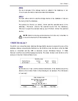
Page 64: ... of the DVR enter the Port Selection menu and assign Text to the Serial Port Then the DVR will now be able to obtain data from the POS system Port Selection 1 Serial Port 2 USB Port Front 3 USB Port Rear Top 4 USB Port Rear Bottom Text None None None Alert Notification Setup This function allows the user to send alert notifications to the CMS program which had been installed to your computer For d...

Page 65: ...ss of the computer Alert Port The ports for DVR and the CMS Alert MUST be the same Alive Interval To define the time interval 1 to 255 seconds between each alive message Event Full Screen This function allows the unit to display the alarm channel in full screen size when an alarm is triggered Select None to disable this function select Main to display the alarm channel on Main Monitor when an alar...

Page 66: ...s users to enable disable Video Loss acknowledged as an alarm event Select ON to enable Video Loss acknowledged as alarm events OFF to disable Motion Detect Use to enable or disable the motion detection function of the Premium H 264 DVR If motion detection function is enabled it is required to define the motion detection parameters such as detection area and sensitivity settings Detection Config I...

Page 67: ...ion alarm will be triggered once the amount of motion detected exceeds the Threshold value Move the cursor to Sensitivity and press ENTER and then use UP DOWN keys to adjust the value The value is increased by 4 increment Area Threshold Area Threshold means the motion alarm triggered level If the percentage of triggered grids from the total detection area is greater than the set value the motion a...

Page 68: ...reen until this item is changed to N O OFF or a device is installed to the unit Alarm Out This item allows users to assign an alarm output on certain channel to activate the relays These signals can be used to drive a light or siren to caution an alarm event The available options and the corresponding activated alarm outs are listed as below table Option Activating Relay Option Activating Relay A ...

Page 69: ... The information is read only Avail Rec Time The Avail REC Time indicates the available time duration for recording If the unit is set to record in circular mode the item will show Circular The information is read only Internal External Disks Select Internal Disks or External Disks to see information of the storage devices connected to the unit For example the Internal Disks menu is displayed as b...

Page 70: ...first NAS Devices The DVR can connect Network Attached Storage NAS devices to expand the size of the database Before connecting the NAS device the DVR has to be shut down After the NAS device is connected and the DVR is rebooted access Database Setup Æ NAS Devices and the menu will be displayed as below The items Active and Action is the same as in Internal External Disks menu NAS Devices Device N...

Page 71: ...tem allows users to load a unit configuration that was saved in an external drive To import a configuration that was previously exported make sure the device that saved the configuration is connected to the unit Select Import Config from the Configuration menu and press ENTER The following menu is displayed Import Config Config Name xxxx xxxx xxx xx Select No No Press UP DOWN to select one of the ...

Page 72: ...ch the configuration can be exported Press UP DOWN to choose a destination Please note that saving a different configuration to the same copy destination with the same file name will overwrite the previous configuration file without warning NOTE Users are not allowed to select any DVD RW as a copy destination including built in DVD RW Configuration Name This item allows users to assign a name to t...

Page 73: ...corded video is exported with digital signature the output will be four files including gpg avi drv sig and readme txt Exporting a file whose size is 1GB with digital signature may take you about 30 minutes From the Main menu select Video Export and press ENTER The following menu is displayed Items in the menu will be described in the following section NOTE The inserted CD DVD will be ejected when...

Page 74: ...with the unit If not please format the HDD to EXT3 format first Device Name The item shows the name of the available device Available The item shows the free space of the available device Sel Set the item to Yes to set it as an exporting destination or No to cancel NOTE The item Erase Disk from Video Export menu will be grayed out when the selected device is not a DVD RW or when the device is not ...

Page 75: ...t export event video only and Both export both normal and event video NOTE If you want to export selected event video using the item Select Event you have to set From and To to the same day and time otherwise not only the selected event video will be exported to the selected destination but also other event video recorded during the period between From and To NOTE You will not be allowed to access...

Page 76: ...e sure that you have an external storage device such as a USB Hard Drive or USB ThumbDrive available and connected to the appropriate port for export For more information on verifying digital signature see Appendix C DVR Player Erase Disc This function is used to remove information found on a CD RW or DVD RW disk prior to exporting new information to the drive Select YES and press ENTER to start d...

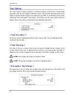
Page 77: ...sed to enable disable this function Select ON the text database will be created on the hard disk Text Overlay This item is for you to choose which mode you want to display the test overlay on the monitor Select Only Live to display the text overlay in Live mode select Only PB to display the text overlay in Playback mode and select Live PB to display in both modes NOTE Text overlay only shows in fu...

Page 78: ...enabled only transactions which meet both Exception String and By Numerals condition will be marked as exceptions and thus trigger an action You can select from the following options OFF The function is disabled Specific The value of transaction meets a specific value will be marked as an exception The specific value needs to be configured through the following sub setting Value Greater Equal Than...

Page 79: ...s been stored before won t be marked as exceptions Input Setup This item is used to choose the connection method between your Text Device and the DVR Also some relative settings of the connection method can be configured Input Setup 1 Port Selection 2 Input Source 3 Camera Selection 4 Text Filter 5 Manual Filter Setup 6 Input Process 7 Text Baud Rate 8 Text Bits 9 Text Stop 10 Text Parity Serial P...

Page 80: ...S300 IBM SurePOS 700 Digipos CD5220 Dell T200 Samsung ER 380M Emax Pole Display Epson TM T88II TM T88III TM T88IV Samsung ER 655 Epson DM D Series Epson TM T90 Senor POS Logic Controls LD9000 Epson TM 930 II Logic Controls PD3000 Epson RP U420 Logic Controls PD6000 IBM SureMark TF6 Logic Controls TD3000 IBM SureMark TM6 Magellan Ithaca iTherm 280 Partnertech CD5220 Ithaca POSJet 1000 Posiflex ICD ...

Page 81: ...using a Pole Display from a PC based POS select Canonical Non Canonical is to be selected when using a Pole Display from a Standalone POS Text Baud Rate This item allows users to setup the baud rate of RS232 which connects your Text Device and the DVR Text Bit This item allows users to setup the bits of RS232 Text Stop This item allows users to setup the stop of RS232 Text Parity This item allows ...

Page 82: ...ain menu and press ENTER to access the Shutdown menu which is displayed as follows Shutdown 1 Power Off 2 Reboot Execute Execute Power Off Select this item to shut down the unit Do not remove the power during shut down until the message You can safely turn off DVR now displays Reboot Select this item to reboot the unit The color bar and system checking information will be displaying on the monitor...

Page 83: ...ration times are based on actual tests and represent average file sizes Performance may vary depending on specific installations and use Audio recording requires 8 KB per second or 0 7 GB per day for data storage Record Duration Days Full D1 Global Day Night Weekend without Audio Recording Rate Recording Quality Mode Low Fair Mid High Best Total PPS of all Channels NTSC PAL NTSC PAL NTSC PAL NTSC ...

Page 84: ...55 85 67 02 39 24 47 09 Record Duration Days CIF Global Day Night Weekend without Audio Recording Rate Recording Quality Mode Low Fair Mid High Best Total PPS of all Channels NTSC PAL NTSC PAL NTSC PAL NTSC PAL NTSC PAL NTSC PAL 2 KB 2 KB 3 KB 3 KB 4 KB 4 KB 5 KB 5 KB 6 KB 6 KB 160 GB Internal Storage 120 100 40 67 48 80 18 18 21 81 10 28 12 34 6 62 7 94 4 62 5 55 60 50 81 33 97 60 36 35 43 62 20 ...

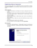
Page 85: ...itoring via the remote software Follow the description below to set up your DVR and PC DVR Configuration Connect an USB modem to the USB socket and connect a working phone line to the modem Press MENU and input correct username and password to access the OSD setup menu Select Network Setup Æ Modem Setup Æ Dial in Setup to set up the Dial In settings including Dial in Account and password etc For m...

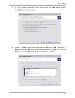
Page 86: ...User s Manual 86 Set up the network connection type Select Connect to the Internet and click Next to continue Select Set up my connection manually and click Next to continue ...

Page 87: ...User s Manual 87 Select Connect using a dial up modem to connect to the internet through phone line and a modem Click Next to continue Type the name of the connection you are creating ...

Page 88: ...User s Manual 88 Enter the phone number of the modem that is connected to the unit Enter the Username and Password that has been set in the Dial in Setup menu ...

Page 89: ...User s Manual 89 Click Finish to complete the dial in connection Now the dial in connection is established ...

Page 90: ...rd to access the OSD setup menu Select Network Setup Æ Modem Setup Æ Dial out Setup to set up the Dial out settings Select the Email Address in Network Setup menu to edit an e mail address for alarm notification Select Event Setup in Main menu and set the Email Notice function to ON enabled Exit the OSD setup menu and save the configuration For more information on dial out settings see Section Dia...

Page 91: ...Manual 91 Set up the network connection type Select Set up an advanced connection and then Accept incoming connections Click Next to continue Choose the modem device that will be used by the PC and click Next ...

Page 92: ...llow virtual private connections and click on Next In User Permission menu select the users who need to use this connection If needed add a new user with the same user password that is set up in Dial out Setup menu in local DVR When it s done click Next to continue ...

Page 93: ... address assignment if the PC has DHCP server then choose Assign TCP IP addresses automatically using DHCP else choose Specify TCP IP addresses and enter the range of IP addresses that you wish to use Once done click OK to confirm and back to Networking Software menu Click on Next to continue ...

Page 94: ...User s Manual 94 Click Finish to complete the process The Incoming connection is established ...

Page 95: ...file to the same folder Click on the DVR_Player exe file and the main window of the DVRPlayer will show up as below The main window of the DVRPlayer displays a list of cameras and mode selection buttons at the left hand side Using the mode selection buttons users can select a desired viewing mode including 4 window 9 window and 16 window The functional items are 1 Audio On Off 5 Capture Snapshot 2...

Page 96: ...ared at the top Note that users can also click Open on the top to select a different folder which contains recorded videos Select one from the list and click Playback at the bottom then the Playback window will be shown as below In the Tool Playback tab users can set starting time and displaying cameras of the selected video Then click OK on the upper right hand corner of the window to start playb...

Page 97: ...ck Open to select a specific drv file and click OK to playback the file on the main window Note If users click the close button at the top right corner of the Data List window the following Playback window with Local Playback tab and Verify tab only The function of Verify tab will be described on the next page ...

Page 98: ...bottom then the Playback window will be displayed returning a GOOD or BAD signature result in the Status Log field A GOOD signature indicates the exported clip has not been altered whereas a BAD signature means the video might be changed at some point Alternatively click Browse to select the gpg drv or avi sig files which belong to the video to be authenticated respectively After all files are sel...

Page 99: ...lick to playback the video backward Click repeatedly to select the desired playback speed from 1X 2X 4X 8X 16X and 32X 2 When the playback is paused click once to move one step backward Play Click to resume the playback The icon is displayed when the playback operation is paused Pause Click to pause the playback The icon is displayed while playing back the video Fast Forward Step Forward 1 Click t...

Page 100: ...User s Manual 100 Appendix D ezRecord Diagram Sample ...

Page 101: ...User s Manual 101 ...

Page 102: ...User s Manual 102 ...

Page 103: ...d the DVR s HDD Installation of the DVR s HDD EXT2IFS can be found on the website http uranus it swin edu au jn linux ext2ifs htm A detailed description about the driver can also be found Plug in the DVR s HDD to the PC then follow the steps below Step 1 Download EXT2IFS to the PC from the website listed above Step 2 Extract the EXT2IFS driver that was just downloaded Open the extracted folder and...

Page 104: ... Step 5 Click Step3 Then click Start Driver button Now reboot the PC for the changes to take effect The HDD installation is now completed After the DVR s HDD is correctly installed videos in the DVR s HDD can be played back by using the DVRPlayer Refer to Appendix C DVRPlayer for detail instruction about the operation of the DVRPlayer 2 1 3 2 1 ...

Page 105: ...en the EXT2IFS and go to Step 1 menu Click Uninstall Driver and a message will be shown as The service is currently started You will have to reboot before the service is completely uninstalled Click on OK and turn off the PC Remove the HDD from the PC and reboot the PC The removal of HDD is now completed 1 2 ...

Page 106: ...ification in the interest of ongoing product development and improvement 2011 Ness Corporation Pty Ltd ABN 28 069 984 372 Head Office Ness Security Products Pty Ltd ABN 28 069 984 372 Ph 61 2 8825 9222 Fax 61 2 9674 2520 ness ness com au Sydney Ph 02 8825 9222 Fax 02 9674 2520 sales ness com au Melbourne Ph 03 9875 6400 Fax 03 9875 6422 nessmelb ness com au Brisbane Ph 07 3399 4910 Fax 07 3217 971...

Reviews: