


5
NOTE: BEFORE USING THE EQUIPMENT, PLEASE READ THIS
MANUAL CAREFULLY AND KEEP IT FOR FUTURE REFERENCE.
PERSONS WHO HAVE NOT READ THE INSTRUCTIONS SHOULD
NOT CARRY OUT ASSEMBLY, ADJUSTMENT OR OPERATION OF
THE EQUIPMENT.
SPECIFIC SAFETY PROVISIONS
NOTE!
Read the operating instructions carefully, follow the warnings and safety
conditions contained therein. The appliance has been designed for safe
operation. Nevertheless: installation, maintenance and operation of the
appliance can be dangerous. Following the following procedures will
reduce the risk of injury and reduce the installation time of the appliance
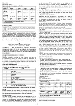
Description of graphic elements
The numbering below refers to the components of the device
shown on the graphic pages of this manual.
Designation
Description
1
Bow
2
Anvil
3
Measuring surfaces
4
Spindle
5
Bushing
6
Spindle lock
7
Sleeve measuring scale
8
Drum measuring scale
9
Drum
10
Clutch
11
Micrometer measuring range
12
Measurement accuracy of the micrometer
* There may be differences between the graphic and the actual
product
PURPOSE
The vernier micrometer, made of high quality steel, is designed for external
measurements within the range it supports. The instrument is
characterised by high precision measurements and their repeatability.
METHOD OF APPLICATION
Before each use, check the measuring surfaces fig. A3 that they are clean
and free of grease residues and metal filings. It is recommended to clean
the measuring surfaces of the anvil fig. A2 and the spindle fig. A4 with a
soft cloth or soft paper, then bring them closer together by carefully turning
the clutch. If the line marked "O" on the drum fig. A8 coincides with the
reference line on the bushing fig. B4 the measurement will be correct and
no adjustment is required. If, on the other hand, the lines do not coincide
require adjustment of the zero position as follows:
1.Deviation 0.01mm
Lock the spindle with the locking device and then adjust the sleeve with a
spanner until the reference line is exactly aligned with the "O" line on the
drum.
2.Deviation greater than +0.01mm
Lock the spindle with the locking device and loosen the ratchet stop with
a spanner. By pressing the drum on the ratchet stop, bring it to a point
where the "O" line coincides with the reference line on the bushing. Fix the
ratchet stop and make the final adjustment.
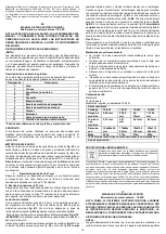
Reading the measurement
One revolution of the drum is 0.5mm. On the measuring scale of the sleeve
above the reference line fig. B4 full millimetres are marked fig. B1. On the
other hand, below the bushing reference line fig. B4 half millimetres are
marked fig. B2.
In order to measure correctly, it is advisable to use the clutch Fig. A10.
ATTENTION! Over-tightening the drum may falsify the measurement and
damage the micrometer.
Insert the object to be measured between the measuring surfaces fig. A3.
Using the drum Fig. A9, bring the anvil Fig. A2 and the spindle Fig. A4 as
close as possible to the object to be measured, and make the last rotation
with the clutch. When the clutch "clatter" is heard, stop turning the knob.
The full millimetre values of the measurement taken are to be read off on
the measuring scale of the sleeve, fig. B1, if they are full and half
millimetres they are to be read off on the scale, fig. B2. When reading the
measurement, pay particular attention to where the edge of the drum is
located fig.C2, fig.D2. If the edge of the drum is in position fig.C1 to the
full millimetres add the reading from the measuring scale of the drum
fig.A8. The measurement result from fig. C is 37.3mm. If the edge of the
drum is in position fig. D1 to half a millimetre we add the reading from the
measuring scale of the drum fig. A8. The result of the measurement from
fig. D is 37.8mm.
We recommend that measurement takes place in good lighting conditions
and that the measuring scales of the drum and sleeve are clean, allowing
the result to be read correctly.
Maintenance and storage
•
The unit should not be disassembled unnecessarily, except for
calibration.
•
Do not drop the micrometer on hard surfaces or drop heavy objects
on the micrometer.
•
Take care of the cleanliness of the device itself, especially the
measuring edges and measuring scales.
•
Store in a dry ventilated place, do not expose to direct sunlight.
•
After long-term storage or when there is no visible layer of protective
oil, carry out appropriate cleaning and maintenance procedures.
•
The micrometer should be stored in a case that. Always leave a gap
of O.1 to 1mm between the measuring surfaces when storing the
micrometer.
Kit contents:
Micrometer
Adjustment key
Length gauge (not applicable to 75-020)
Rated data
Catalogue
75-020
75-021
75-022
75-023
Measurem
ent range
0-25mm
25-
50mm
50-
75mm
75-100mm
Measurem
ent
tolerance
0.01mm
0.01mm
0.01mm
0.01mm
Dimensio
ns
140x60x25
mm
170x80
x25 mm
195x100
x25 mm
220x110
x25 mm
Mass
240g
370g
470g
660g
75-02X indicates both the type and the designation of the device
Year of production
ENVIRONMENTAL PROTECTION
The product should not be thrown away with household waste, but
should be disposed of at suitable facilities. A non-recycled product is a
potential danger to the environment and human health.
"Grupa Topex Spółka z ograniczoną odpowiedzialnością" Spółka komandytowa with its
registered office in Warsaw, ul. Pograniczna 2/4 (hereinafter: "Grupa Topex") informs that
all copyrights to the content of this manual (hereinafter: "Manual"), including, among
others. Its text, photographs, diagrams, drawings, as well as its composition, belong
exclusively to Grupa Topex and are subject to legal protection under the Act of 4 February
1994 on Copyright and Related Rights (ie Journal of Laws 2006 No. 90 Poz. 631, as
amended). Copying, processing, publishing, modifying for commercial purposes the entire
Manual and its individual elements, without the consent of Grupa Topex expressed in
writing, is strictly prohibited and may result in civil and criminal liability.
DE
ÜBERSETZUNG (BENUTZERHANDBUCH)
Äußeres Feinmessgerät : 75
-02X
HINWEIS: BEVOR SIE DAS GERÄT BENUTZEN, LESEN SIE BITTE
DIESE ANLEITUNG SORGFÄLTIG DURCH UND BEWAHREN SIE SIE
ZUM NACHSCHLAGEN AUF. PERSONEN, DIE DIE ANLEITUNG
NICHT GELESEN HABEN, DÜRFEN DAS GERÄT NICHT
ZUSAMMENBAUEN, EINSTELLEN ODER BEDIENEN.
BESONDERE SICHERHEITSBESTIMMUNGEN
HINWEIS!
Lesen Sie die Bedienungsanleitung sorgfältig durch, beachten Sie die
darin enthaltenen Warnhinweise und Sicherheitsvorschriften. Das Gerät
wurde für einen sicheren Betrieb konzipiert. Dennoch: Installation,
Wartung und Bet
rieb des Geräts können gefährlich sein. Die Einhaltung
der folgenden Verfahren verringert das Verletzungsrisiko und verkürzt die
Installationszeit des Geräts
Beschreibung der grafischen Elemente
Die folgende Nummerierung bezieht sich auf die Komponenten des
Geräts
die auf den grafischen Seiten dieses Handbuchs dargestellt sind.
Bezeichnung
Beschreibung
1
Bogen
2
Amboss
3
Messflächen
4
Spindel


