5. Installing Optional Devices
Express5800/R310e-E4, R320e-E4, R320e-M4, R310f-E4, R320f-E4, R320f-M4 Maintenance Guide (Windows)
186
Chapter 2 Configuring and Upgrading the System
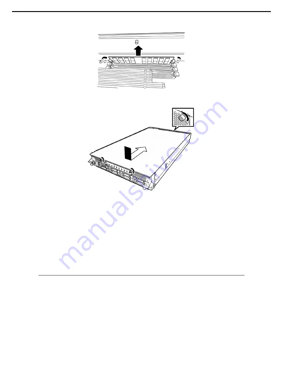
6. Press the levers on both sides of the DIMM slot to release the lock, and remove the DIMM.
7. Install the air duct.
8. Place the top cover of the CPU/IO module and secure it with three screws.
9. See
Chapter 2 (5.4.2 Installing CPU/IO Module)
and install the CPU/IO module.
10. Connect the power cords.
11. Press the POWER switch to power on the server.
12. Confirm that POST displays no error message.
If POST displays an error message, write it down and see the POST error message list in
Chapter 1 (6.2
POST Error Messages)
.
13. After starting the OS, set the paging file size to at least the recommended value (1.5 times the installed
memory size). For details, see
Chapter 1 (3.1 Before Starting Setup)
in
Installation Guide (Windows)
, or
Chapter 1 (4.1 Before Starting Setup)
or
Chapter 1 (5.1 Before Starting Setup)
and
Chapter 1 (6.1
Memory Dump (Debug Information)
.)
5.5.3
Replacing DIMM
Follow the steps below to replace a failed DIMM.
1. Refer to
Chapter 1 (6.1 Error Indication by LED)
to check the faulty DIMM when the memory slot error
LED lights up.
2. Remove the CPU/IO module according to
Chapter 2 (5.4.1 Removing CPU/IO Module)
.
3. Replace the DIMM.
4. See
Chapter 2 (5.4.2 Installing CPU/IO Module)
and install the CPU/IO module.
5. Start up the CPU/IO module using NEC ESMPRO Manager or ft server utility.
Summary of Contents for Express5800/R310e-E4
Page 267: ...MEMO...


