-
16
-
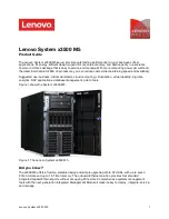
140He Front View (with the Front Door Open)
1
3.5-inch floppy disk drive
Insert a 3.5-inch floppy disk to the 3.5-inch floppy disk drive to read data from the
disk or write data to the disk.
1-1: Eject button
1-2: Disk slot
1-3: Floppy disk access lamp (lit green during accessing)
2 CD-ROM
drive
The CD-ROM drive reads data from the inserted CD-ROM.
2-1: Emergency eject hole
2-2: CD Tray eject button
2-3: Access lamp
(lit orange during accessing)
3
3.5-inch disk bay
The 3.5-inch hard disk bay contains additional hard disk slots. 1-inch thick hard disk
drives can be inserted into the slots. The number following the bold-faced character
indicates the SCSI ID.
4 Processor
board
4-1: Processor board ejector
5 Memory
board
5-1: Memory board ejector
5-2: Memory board Power lamp
5-3: Memory board Attention lamp
5-4: Memory board Redundancy lamp
5-5: Memory board Attention switch
6
Additional memory board slot
7
5.25-inch device bay
DAT (digital audio tape) drive or optical disk drive may be installed in the 5.25-inch
device bay. Slot #1 (right) and slot #2 (left).
1
2
-1
2
-2
2
-3
1
-2
1
-3
1
-1
2
3
4
7
3
-0
3
-1
3
-2
3
-3
3
-4
4
-1
5
5
-1
5
-2
5
-3
5
-4
5
-5
6
Summary of Contents for EXPRESS5800/140He
Page 1: ...Nec coF S e r v i c e G u i d e EXPRESS5800 140He EXPRESS5800 140Rd 4 ...
Page 2: ...This page is intentionally left blank ...
Page 4: ...This page is intentionally left blank ...
Page 144: ... 128 8 2 3 Processor and VRM Processor 1 Processor 2 Processor 4 Processor 3 ...
Page 153: ... 137 voltage drop and the system is restarted This is not an error ...
Page 161: ... 145 No Error message Action 8 The firmware is erased unsuccessfully ...
Page 163: ... 147 ...
Page 181: ... 165 12 3 Block Diagram ...
Page 182: ... 166 This page is intentionally left blank ...
Page 183: ... 167 This page is intentionally left blank ...
Page 184: ... 168 ...