background image


Configuration Installation Guide 


Bookshelf Configuration 


This document provides important information for installing and removing the bookshelf configuration.  

Install the bookshelf configuration 

To install the bookshelf configuration, complete the following steps. 

Note: 

Reserve 500 mm empty space in front of the node so that you can have sufficient space to install and remove the node.
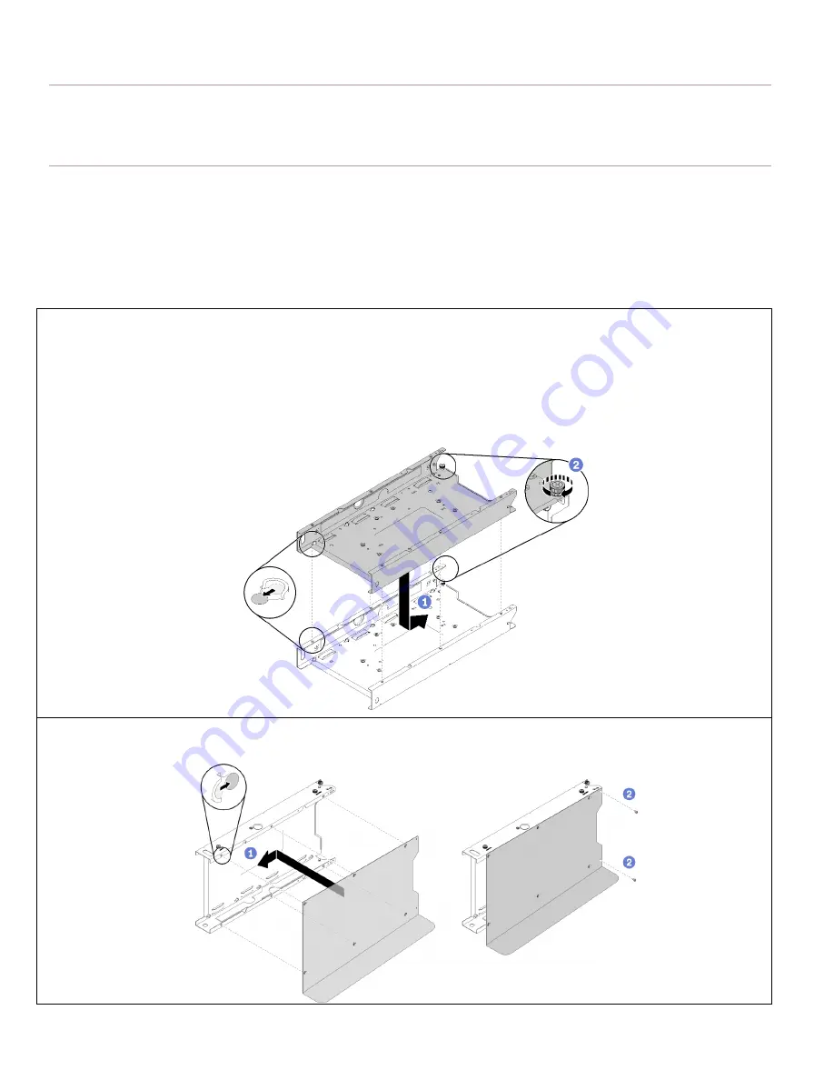
 

1. 

If you would like to stack your nodes,


complete the following steps. 

 Hook the six T-pins into place and slide the node sleeve backward.  

 Fasten the thumbscrew. 

 Repeat step 

 and step 


to stack your node sleeves.  

Note:

 Bookshelf supports up to three node stacks.  


2. 

Align the right bookshelf with the node sleeve and slightly push the bookshelf leftward to hook the six T-pins into place; then, 
fasten the two screws. 


Summary of Contents for SE350

Page 1: ...e in front of the node so that you can have sufficient space to install and remove the node 1 If you would like to stack your nodes complete the following steps Hook the six T pins into place and slide the node sleeve backward Fasten the thumbscrew Repeat step and step to stack your node sleeves Note Bookshelf supports up to three node stacks 2 Align the right bookshelf with the node sleeve and sl...

Page 2: ... node sleeve and slide the node into place then fasten the two thumbscrews Repeat the steps if you have more nodes to install 5 Carefully insert the tab on the security bezel into the slot then pivot the security bezel inward until the other side clicks into place 6 Use the key to lock the security bezel 7 Repeat the step 5 and step 6 if you have more security bezels to install ...

Page 3: ...3 8 If you need to install the lock position switch please refer to the Maintenance Manual Otherwise carefully place your machines as the following illustration ...

Page 4: ...sufficient space to install and remove the node 1 Use the key to unlock the security bezel 2 Press the release tab and pivot the security bezel outward to remove it from the node sleeve 3 Repeat the step 1 and step 2 if you have more security bezels to remove 4 Loosen the two thumbscrews and slide the node out of the node sleeve Repeat the step if you have more nodes to remove ...

Page 5: ... 6 Slightly push the right bookshelf rightward to unhook the six T pins then remove the right bookshelf 7 Remove the two screws 8 Slightly push the left bookshelf leftward to unhook the six T pins then remove the left bookshelf ...

Page 6: ...9 Remove the node sleeve if necessary Loosen the thumbscrew and slide the node sleeve frontward to unhook the six T pins then remove the node sleeve Repeat the step if you have more node sleeves to remove ...

Page 7: ... clips to the power adapter bracket or the node sleeve depending on your configuration If you are installing the node sleeve without the power adapter bracket complete the following steps Align the two DIN rail clips with the node sleeve Insert and tighten the four screws If you are installing the node sleeve with the power adapter bracket complete the following steps Align the two DIN rail clips ...

Page 8: ...ails at an angle 3 Put down the node sleeve and ensure the DIN rail clips are securely seated 4 Install the Screws to secure the power adapter bracket Note You can install the screws vertically or horizontally according to your DIN rail setting ...

Page 9: ...ket then slide the power adapters into place Align the tab with the slot and carefully hook the tab into place Fasten the thumbscrew Align the node sleeve with the power adapter bracket and slightly push the node sleeve downward to hook the four T pins into place Insert and tighten the four screws ...

Page 10: ...de into place then fasten the two thumbscrews 7 Connect the cables if necessary 8 Carefully insert the tab on the security bezel into the slot then pivot the security bezel inward until the other side clicks into place 9 Use the key to lock the security bezel ...

Page 11: ...ce in front of the node so that you can have sufficient space to install and remove the node 1 Use the key to unlock the security bezel 2 Press the release tab and pivot the security bezel outward to remove it from the node sleeve 3 Disconnect the cables if necessary 4 Loosen the two thumbscrews and slide the node of the node sleeve ...

Page 12: ...ur screws Slightly push the node sleeve upward to unhook the four T pins and remove it from the power adapter bracket Loosen the thumbscrew Remove the tab from the power adapter bracket Slide the power adapters out of the power adapter bracket ...

Page 13: ...13 6 Remove the screws from the power adapter Note You can remove the screws horizontally or vertically as below according to your DIN rail setting 7 Pull the node sleeve up and remove it from the rails ...

Page 14: ...leeve without the power adapter bracket remove the two DIN rail clips by removing four screws If you are removing the node sleeve with the power adapter bracket complete the following steps Remove the four screws then remove the two DIN rail clips Note You can remove the DIN rail clips vertically or horizontally according to your DIN rail setting ...

Page 15: ...g the server on a wall that has 200x200 and 100x100 threaded holes M4 purchase suitable M4 screws and nuts by yourself first then fasten the node sleeve or the power bracket to the VESA or to the wall For VESA mount and threaded wall skip step 1 3 and go to step 5 or step 6 depending on your configuration 1 Place the node sleeve or the power adapter bracket on the wall 2 Use a pencil to mark the s...

Page 16: ...acket place the power adapter bracket on the wall and mark the screw positions as the following illustration 4 Insert and tighten four wall anchors to the wall Note If the wall anchors are not needed for your configuration skip this step and fasten the required screws ...

Page 17: ...te the following steps Align the node sleeve with the holes on the wall Insert and tighten the four screws If the wall anchors are installed then install the four tapping screws If the wall anchors are not needed then install four machine screws Note The machine screws are not included in the package you need to purchase them by yourself ...

Page 18: ...wer adapter bracket with the holes on the wall Insert and tighten the four screws If the wall anchors are installed then install the four tapping screws If the wall anchors are not needed then install four machine screws Note The machine screws are not included in the package you need to purchase them by yourself ...

Page 19: ...wer adapters into place Align the tab with the slot and carefully hook the tab into place Fasten the thumbscrew Align the node sleeve with the power adapter bracket and slightly pull the node sleeve downward to hook the four T pins into place Insert and tighten the four screws ...

Page 20: ...de into place then fasten the two thumbscrews 7 Connect the cables if necessary 8 Carefully insert the tab on the security bezel into the slot then pivot the security bezel inward until the other side clicks into place 9 Use the key to lock the security bezel ...

Page 21: ...pace in front of the node so that you can have sufficient space to install and remove the node 1 Use the key to unlock the security bezel 2 Press the release tab and pivot the security bezel outward to remove it from the node sleeve 3 Disconnect the cables if necessary 4 Loosen the two thumbscrews and slide the node out of the node sleeve ...

Page 22: ...leeve and the power adapter bracket If you are removing the node sleeve without the power adapter bracket complete the following steps Remove the four screws Remove the node sleeve from the wall or the power adapter bracket ...

Page 23: ...e the following steps Remove the four screws Slightly pull the node sleeve upward to unhook the four T pins and remove it from the power adapter bracket Loosen the thumbscrew Remove the tab from the power adapter bracket Slide the power adapters out of the power adapter bracket ...

Page 24: ...S NOTICE If data or software is delivered pursuant to a General Services Administration GSA contract use reproduction or disclosure is subject to restrictions set forth in Contract No GS 35F 05925 Product and service names appearing herein are trademarks or service marks of their respective owners Printed in China 1P P N SP47A57498 ...

Reviews: