3-18
Installing Server
Connect peripheral devices to NEC Express5800/ft series
The server provides connectors for a wide variety of peripheral devices on its front and rear.
The figure on the next page illustrates available peripheral devices for the server in the standard
configuration, and locations of the connectors for the devices. After connecting the peripheral
devices, connect the provided power cords with the server, and then plug the power cords into the
power outlet.
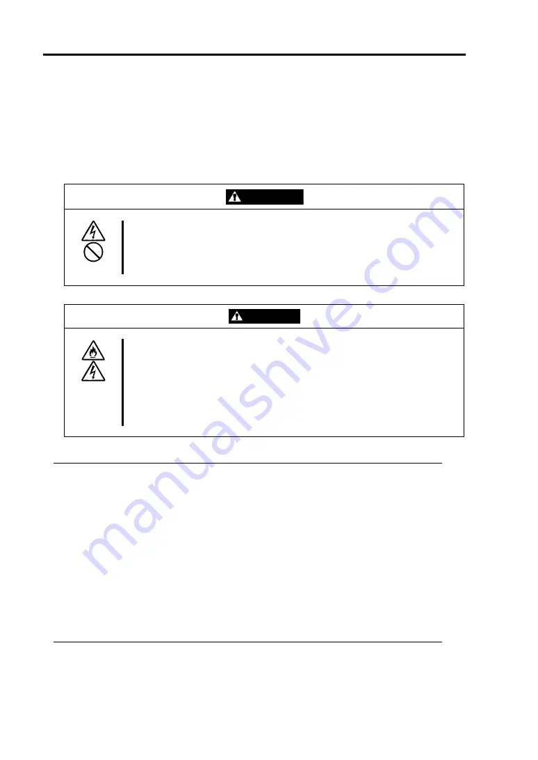
WARNING
Observe the following precautions to use the server safely. There is a risk of a
death or serious injury. For details, see
“
Notes for Safe Handling
“
in Chapter 1.
Do not hold the power plug with a wet hand.
Do not connect the ground wire to a gas pipe.
CAUTION
Observe the following precautions instructions for the safe use of the
equipment. There is a risk of a burn, personal injury, or damage to physical
assets. For details, see
“
Notes for Safe Handling
“
in Chapter 1.
Do not plug the power cord in a nonconforming outlet.
Do not plug too many cords in a single outlet.
Do not plug the cord insecurely.
Do not use nonconforming power cords.
IMPORTANT:
Power off the server before connecting peripheral devices, with the exception of
peripherals with USB interface. Connecting a powered peripheral device to the powered
server will cause malfunctions and failures.
To connect a third-party peripheral device or interface cable to the server, check with
your sales agent to see if they are compatible with NEC Express5800/ft series. Some
third-party devices may not be used with the server.
The total cable length of SCSI device connections is up to 6 m, including the internal
SCSI cables.
The serial port connectors are reserved for maintenance.
Place the USB floppy disk drive on the server. Space of 1U is needed to put it on the
server.
Summary of Contents for EXP320K
Page 11: ......
Page 38: ...1 22 Before Using This page is intentionally left blank ...
Page 80: ...4 20 ESX Server Setup 1 10 Enter LUN Hex select 00 1 11 Select Boot LUN select 01 ...
Page 108: ...5 16 Procedures after Completion of Installation This page is intentionally left blank ...
Page 112: ...6 4 Troubleshooting This page is intentionally left blank ...
Page 114: ......
Page 115: ......


