background image

Database Transfer Utility

5-6

Section 5: Maintenance Options and SMDR

DS1000 Hardware Manual

Database Transfer  Utility

About the Database Transfer Utility

The Database Transfer Utility allows you to transfer the contents of one DS1000 system (called the source) 
to another DS1000 system (called the destination). All programming is transferred, including user-set 
options such as Personal Speed Dial, Distinctive Ringing and custom Volume/Contrast Control settings. 

Software version 03.**.** databases are not compatible with any prior 02.**.** versions.

Connecting the Systems

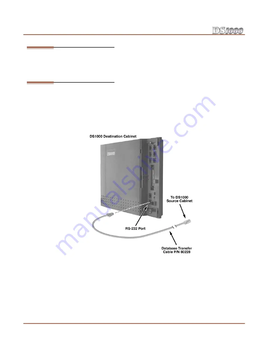
To connect the DS1000 systems for Database Transfer

 (Figure 5-5)

:

1.

Be sure both systems are turned on and operating properly.

2.

Check the source system programming to be sure the con

fi

guration you are going to transfer is correct.

3.

Plug one end of the special Database Transfer Cable (P/N 80228) into the RS-232 port of the destina-

tion system (i.e., the system that will 

receive

 the new programming).

4.

Plug the other end of the Database Transfer Cable (P/N 80228) into the RS-232 port of the source sys-

tem (i.e., the system that currently has the programming you want to transfer.

Figure 5-5: Setting Up Database Transfer

Summary of Contents for DS1000

Page 1: ...ew features will not be available If upgrading from version 3 software prior to 03 10 08 using telephone program ming you must reprogram the options in 1808 IntraMail Subscriber Mailbox Options 8005 I...

Page 2: ...Solutions Inc has no obligation to provide any updates or corrections to this manual Further NEC Unified Solutions Inc also reserves the right without prior notice to make changes in equipment design...

Page 3: ...the Top Panel 1 7 Power Supply AC Input Fuses 1 8 Installing and Replacing the Battery 1 9 Replacing the Battery 1 9 Installing the Expansion Board 1 10 Section 2 Trunk and Extension Cabling 2 1 Befo...

Page 4: ...Through 4 7 DSS Console 4 8 Installing a DSS Console 4 8 Programming DSS Consoles 4 8 2 OPX Module 4 10 Installing the 2 OPX Module 4 10 Programming 2 OPX Modules 4 11 Wall Mounting the 2 OPX Module 4...

Page 5: ...abase Transfer Utility 5 6 About the Database Transfer Utility 5 6 Connecting the Systems 5 6 Important Database Transfer Utility Notes 5 7 Using the Database Transfer Utility 5 7 Section 6 Specificat...

Page 6: ...Table of Contents iv Table of Contents DS1000 Hardware Manual...

Page 7: ...e common equipment extensions the telco demarcation and earth ground In addition the installation site must meet the requirements outlined in the Standard Practices Manual Site Requirements The common...

Page 8: ...ee below Extension Numbers Extension numbers allow you to access the stations and trunks By default each station and trunk num ber has an extension number assigned to it You can change these assignmen...

Page 9: ...1 Item 1 must always be equal to or less than the entry in Item 2 Voice Mail Ports Ports Station Numbers Extension Numbers 201 208 500 507 UCD Groups Total Groups UCD Group Master Extension Numbers 8...

Page 10: ...exceed 4 Ringer Equivalence is cumulative By default all analog telephones ring simultaneously for outside calls as do all analog telephones con nected to the same port This means you must add up all...

Page 11: ...standard installation practices and local codes The equipment cabinet requires a three prong dedicated 110 VAC 60 Hz circuit NEMA 5 15 receptacle located within 4 1 2 feet of the cabinet s lower left...

Page 12: ...Slide the cover button to OPEN 2 Slide the cover away from the Main Equipment Cabinet Hanging the Cabinet To hang the cabinet Figure 1 3 1 Screw suitable fasteners 11 3 16 apart in a convenient locat...

Page 13: ...e power supply AC input fuses In the event of commercial AC power failure the battery provides short term backup of system memory and the system time and date Real Time Clock The battery will hold mem...

Page 14: ...he detail in the illustration above protect the system power supply from problems with the site s AC line These problems can include improperly wired outlets and power surges In normal operation you s...

Page 15: ...move the battery programmed data and the Real Time Clock will reset to the factory installed default settings 2 Following Figure 1 6 gently push down on the battery and remove it 3 Replace the battery...

Page 16: ...d Figure 1 7 1 Be sure your system s power cord is unplugged The Expansion Board is not hot swappable 2 Plug in the Expansion Board as shown below Be sure to snap the Expansion Board into the plastic...

Page 17: ...block and a second 66M1 50 cross connect block for connecting digital and analog extensions Important Install telephones connected to the Main Equipment Cabinet as on premise extensions only Do not p...

Page 18: ...the pinouts for each mod jack Figure 2 2 Mod Jack Assignments Figure 2 3 Mod Plug Pinouts WHT BLK RED GRN YEL BLU CO 1 3 3T 2T 1R 1T 2R 3R WHT BLK RED GRN YEL BLU Audio NC Music T Page R Page T Music...

Page 19: ...BLU BLU YEL YEL ORN ORN YEL YEL GRN GRN YEL YEL BRN BRN YEL YEL SLT SLT YEL VIO BLU BLU VIO VIO ORN ORN VIO VIO GRN GRN VIO VIO BRN BRN VIO VIO SLT SLT VIO 1 2 3 4 5 6 7 8 9 10 11 12 13 14 15 16 17 18...

Page 20: ...The Extension Block 2 4 Section 2 Trunk and Extension Cabling DS1000 Hardware Manual...

Page 21: ...lco may provide your trunks in a single RJ 25C jack or in multiple RJ 11C jacks Review the illustration below 2 Wire the additional modular jacks as shown 3 Plug line cords from the telco mod jacks to...

Page 22: ...cable from the cross connect block to the modular jack 3 Terminate the station cable WHT BLU BLU WHT leads to the RED and GRN lugs in the modular jack 4 Back at the main equipment location run one pa...

Page 23: ...re 3 4 1 Make sure the system is properly grounded 2 Install a surge protector in the AC outlet 3 Plug the main cabinet s AC power cord into its surge protector 4 Be sure the Mode Switch is set to RUN...

Page 24: ...on Reinstalling the Cover Now that your cabling is complete and the system is up and running you should reinstall the cover To reinstall the cover Figure 3 5 1 Slide the cover onto the Main Equipment...

Page 25: ...e the connected Paging equipment is compatible with the following page output specifications To connect an External Paging amplifier Figure 4 1 1 Connect the external Paging amplifier to the GRN and R...

Page 26: ...Zone 1 and All Call Paging announcements broadcast from the External Paging output Additional Programming To adjust the External Paging ring volume In 0202 Page Ring Volume adjust the volume of ringi...

Page 27: ...wering the Door Box chimes the extension user can press FLASH or a soft key to enable the Analog Door Box s relay which in turn unlocks the door The Analog Door Box is a weather tight unit with an ope...

Page 28: ...ing Group to which the Door Box belongs For example if the Door Box and extensions 301 and 302 are in Ring Group 1 pressing the call button alerts 301 and 302 In 1802 Ring Group Number assign the Door...

Page 29: ...handset and press ICM 2 Dial the Door Box extension number To answer the Door Box chimes from a keyset 1 Lift handset or press SPK To control the system relay which in turn controls the door strike On...

Page 30: ...ic In 0201 Background Music enter Y to enable Background Music system wide In 1802 BGM enter Y to enable Background Music at the extension To turn Background Music on and off 1 Do not lift the handset...

Page 31: ...1 Connect the power failure telephone See the illustration below 2 Power down the system 3 At the Power Failure Telephone lift the handset You should hear dial tone from trunk 1 4 Place a test call If...

Page 32: ...le attach the metal plate to both the DSS Console and telephone See Figure 4 5 Installing a 24 Button DSS Console on page 4 8 for more Programming DSS Consoles 1801 DSS Type For the extension to which...

Page 33: ...DSS Console DS1000 Hardware Manual Section 4 Optional Equipment 4 9 4 Figure 4 6 Installing a 110 Button DSS Console 80000 44A To 625 Modular Jack DSS Console Keyset...

Page 34: ...one pair 24 AWG station cable from the cross connect block to the modular jack 3 Terminate the station cable WHT BLU BLU WHT leads to the RED and GRN lugs in the modular jack 4 Back at the main equip...

Page 35: ...on 27 the secondary station s extension number will be 326 Refer to 9902 Set Up Stations DS1000 in the Software Manual on the System Document CD that came with your system for more Note You must set u...

Page 36: ...beneath the telephone s hookswitch Wall Mounting a Key Telephone To mount the telephone on the wall Figure 4 10 1 Using the screws provided attach the wall mount bracket to the wall in the desired loc...

Page 37: ...nt bracket and snap into place To remove the telephone from the wall mount bracket Figure 4 12 1 From the front of the phone grab the tabs that secure the telephone to the wall mount bracket 2 While p...

Page 38: ...ne of two positions low and high To use the desk stand low position Figure 4 13 Flip up each telephone leg until it snaps into place To use the desk stand high position Figure 4 13 1 Flip up each tele...

Page 39: ...ne base remove the plastic molding that covers the hole for the REJ con nector You only need to remove the top half of the molding 5 Install the REJ as shown with the components facing down 6 Secure w...

Page 40: ...REJ Recording Jack 4 16 Section 4 Optional Equipment DS1000 Hardware Manual Figure 4 14 Installing the REJ 80000 48 To mono AUX input on amplifier Red wire...

Page 41: ...ug the telephone line cord 2 While pressing HOLD plug the telephone back in All the LED elements in the display will fill 3 Release HOLD 4 Dial 1 to test the green LEDs in the keys 5 Dial 2 to test th...

Page 42: ...Keyset Self Test 4 18 Section 4 Optional Equipment DS1000 Hardware Manual...

Page 43: ...stem s RS 232 serial port The Call History provides data on system activity Technical Support personnel can use this data to evaluate system performance To connect the PC or laptop to your system Figu...

Page 44: ...rify the connection lift the handset or use features at any telephone History data will dis play on the PC or laptop screen 8 Once you have verified that everything is working OK press Shift 1 again t...

Page 45: ...ns parameters of the system s serial port are 19200 8 N 1 19200 baud eight data bits no parity and 1 stop bit If you have a PC connected to collect history data press Shift 1 to turn history on and of...

Page 46: ...RD TD CTS RTS DTR DCD DSR SG TD RD RTS CTS R1 DB 9 4 1 6 5 3 2 7 8 9 8 9 6 5 1 Mod 8 to 9 Pin Connector for PC Laptop Connection 80200 36 1 8 14 25 1 13 Mod 8 to 25 Pin Connector for Modem Connection...

Page 47: ...m You may need to reset your system for troubleshooting purposes To reset your system Figure 5 4 1 Make sure the RUN LOAD switch is set to RUN 2 Following the illustration below press the red reset sw...

Page 48: ...ases are not compatible with any prior 02 versions Connecting the Systems To connect the DS1000 systems for Database Transfer Figure 5 5 1 Be sure both systems are turned on and operating properly 2 C...

Page 49: ...tomatically reset and auto ID all connected station devices Using the Database Transfer Utility Important Follow these steps exactly as written 1 Make sure the destination system is idle 2 On the dest...

Page 50: ...led 9 When the Database Transfer completes set the MODE switch on the source system back to RUN and press the red reset button 10 To repeat the Database Transfer procedure you must start over again fr...

Page 51: ...ital Telephones Base 8 Expansion 8 Total 16 Analog Telephones Base 4 Expansion 4 Total 8 Door Boxes analog Base 1 Expansion 1 Total 2 Power Failure Telephones 1 DSS Consoles 1 max per keyset 4 max per...

Page 52: ...or other fluids come in contact with the main equipment 5 In areas near high frequency machines or electric welders 6 Near computers telexes microwaves air conditioners etc 7 Near radio antennas incl...

Page 53: ...ypical depending on telephone type and loop length Ringing voltage 50 70 VAC sine wave Trunk Voltages Ringing voltage 42 103 VAC 20 Hz Battery from telco 44 56 VDC External Paging Output Impedance 600...

Page 54: ...hz REJ Recording Jack Output Specifications Output Impedance 200 Ohms Output Level into 10K Ohm load Keyset volume setting 1 7 8 dBr Keyset volume setting 7 5 3 dBr The REJ broadcasts both sides of th...

Page 55: ...uit 2 When cables must be run on the floor use cable protectors 3 Cable runs for key telephones single line telephones Door Boxes and 2 OPX Modules must be a dedicated isolated cable pair Device Cable...

Page 56: ...play Telephone 80573 24 Button DSS Console 80556 110 Button DSS Console 80555 Wall Mount Kit 80579 Analog Telephones customer provided Peripheral Station Equipment Description Part Number Analog Door...

Page 57: ...over 80600 34 34 Button Super Display Clear Plastic Cover 80600 S34 110 Button DSS Clear Plastic Cover 80600 DSS 24 Button DSS Clear Plastic Cover 80600 24DSS Directory Tray 92602 9 Handset Coil Cord...

Page 58: ...Parts List 6 8 Section 6 Specifications and Parts DS1000 Hardware Manual...

Page 59: ...er Utility 5 6 DSS Console 4 8 DSS Console Programming 4 8 E Electrical Specifications 6 2 6 3 Environmental Requirements 6 2 Environmental Specifications 6 2 Expanded Database 1 2 Extension Block 2 3...

Page 60: ...eplacing the Fuses 1 8 Resetting Your System 5 5 S Single Line Telephone REN Limitations DS1000 1 4 Site Requirements 1 1 SMDR 5 1 SMDR Programming 5 2 Specifications 6 1 Station Equipment 6 6 System...

Page 61: ...ns com Other Important Telephone Numbers Sales 203 926 5450 Customer Service 203 926 5444 Customer Service FAX 203 926 5454 Technical Service 203 925 8801 Discontinued Product Service 900 990 2541 Tec...

Page 62: ...80200INS05 80200INS05 February 5 2005 Printed in U S A NEC Unified Solutions Inc 4 Forest Parkway Shelton CT 06484 TEL 203 926 5400 FAX 203 929 0535 www necunifiedsolutions com...

Reviews: