Chapter 3: Installing Optional Hardware Features
3-65
3.
Remove the printer.
Note:
The peripheral cables can be left connected if you have
enough work space beside the 7452 to lay the peripheral modules.
4.
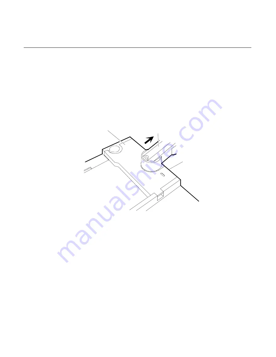
Rotate the Operator Display Arm so that it points 90
o
away from the
workstation. Pry the side of the Display Access Cover out from the
Base Unit slightly and lift it off.
14326
Display Access Cover
Rotate the Display Arm to 90 degrees
from the Base Unit.
Pry the side
of the Display
Cover out and
lift the cover
off.
Summary of Contents for 7452
Page 1: ...NCR 7452 Workstation Release 3 1 Hardware User s Guide BD20 1373 C Issue J...
Page 6: ...iv...
Page 18: ......
Page 44: ...1 26 Chapter 1 Product Overview 14406a Integrated 2x20 Customer Display...
Page 58: ...2 2 Chapter 2 Workstation Hardware Installation AC Input Selection Switch 14598 115V...
Page 74: ...2 18 Chapter 2 Workstation Hardware Installation 14566 Wrap Stand 5952 DynaKey Configuration...
Page 77: ...Chapter 2 Workstation Hardware Installation 2 21 17320 Wrap Stand 5953 DynaKey Configuration...
Page 80: ......
Page 164: ......
Page 187: ...Chapter 4 Setup 4 23 Load Previous Values Save Changes...
Page 216: ...4 52 Chapter 4 Setup...
Page 226: ......
Page 232: ...6 6 Chapter 6 BIOS Updating Procedures 4 After a successful BIOS update reboot the workstation...
Page 256: ......
Page 261: ...BD20 1373 C February 2001 Printed on recycled paper...


