7193 Service Guide
Chapter 2: Installing the Printer
August 1998
7
Note:
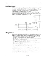
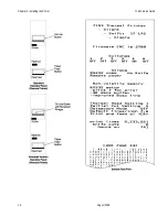
Switch #1 is used to toggle between regular communication with the host computer
and Level 1 Diagnostics (used for the printer functions and level 1 diagnostic tests):
•
Switch #1 set to OFF: printer is ready to communicate with the host computer and
receive data (online mode)
•
Switch #1 set to ON: printer is in Level 1 Diagnostics (setup mode)
If you want the printer to communicate with the host computer, be sure switch 1 is OFF.
Use a paper clip or other pointed object to set the switch.
For additional information on the setup mode (Level 1 Diagnostics), see the “Diagnostics”
chapter.
Note:
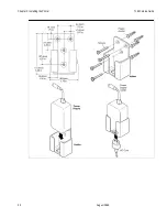
Some 7193 models may appear slightly different than what is shown in the
illustration. The procedures are the same for all models unless otherwise noted.
Summary of Contents for 7193
Page 1: ...BD20 1440 A Issue B August 1998 NCR 7193 Thermal Receipt Printer Service Guide ...
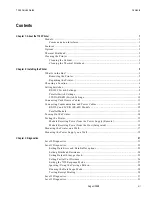
Page 6: ...Contents 7193 Service Guide August 1998 x ...
Page 10: ...Chapter 1 About the 7193 Printer 7193 Service Guide August 1998 4 ...
Page 19: ...7193 Service Guide Chapter 2 Installing the Printer August 1998 13 Parallel Models ...
Page 22: ...Chapter 2 Installing the Printer 7193 Service Guide August 1998 16 ...
Page 24: ...Chapter 2 Installing the Printer 7193 Service Guide August 1998 18 ...
Page 26: ...Chapter 2 Installing the Printer 7193 Service Guide August 1998 20 ...
Page 38: ...Chapter 3 Diagnostics 7193 Service Guide August 1998 32 ...
Page 66: ...Appendix B Ordering Paper and Supplies 7193 Service Guide August 1998 60 ...
Page 78: ...Appendix E Commands 7193 Service Guide August 1998 72 ...
Page 83: ......

