8
MultiVOIP 200 User Guide
Typical Application
Before Voice Over IP (VOIP), voice over the Internet, a corporate office had a data connection to the
Internet and a voice connection to the public telephone network. With VOIP, the two networks can be
tied together. To accomplish this, a MultiVOIP is connected between the public telephone network
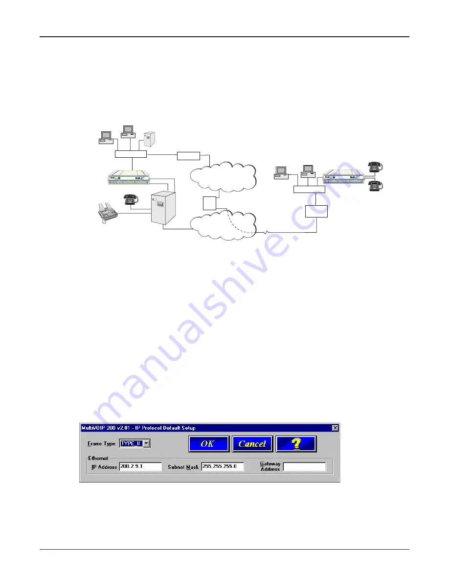
and the data network. A typical application for a MultiVOIP is shown in Figure 1-2.
Remote Branch
Office
Internet/Intranet
IP Network
Corporate Office
P
B
X
PSTN Connection
(T1/E1, PRI, etc.)
Web Server
Workstation
Workstation
MultiVOIP
IP Address
204.22.122.118
Mask 255.255.255.128
LAN
ISP
PSTN
Workstation
Workstation
LAN
Analog Connections
Channel 1: FXO
Channel 2: FXO
Router
IP Address 204.22.122.1
Mask 255.255.255.128
MultiVOIP
IP Address 202.54.39.100
Mask 255.255.255.240
ProxyServer
IP Address 202.54.39.97
Mask 255.255.255.240
#301
#302
ProxyServer Static
IP Address 209.96.211.90
512-4122
512-4123
4124
102
101
Router
4125
Proxy
Server
HUB
HUB
Figure 1-2. Typical VOIP Application
Now, to set up the VOIP network, a MultiVOIP at the corporate office is connected between the data
network and the corporate telephone switch (PBX). To connect the MultiVOIP to the data network, an
Ethernet cable is connected to the Ethernet port on the MultiVOIP and the other end of the cable is
plugged into a hub on the data network. On the phone side, two special adapter cables are
connected to the FXO jacks on the back of the MultiVOIP and run to two station lines on the phone
switch. These two lines on the PBX occupy phone extensions 4124 and 4125.
To set up a MultiVOIP at the remote branch office, the Ethernet jack on the MultiVOIP is connected to
the hub and two special adapter cables are connected between the FXS jacks on the MultiVOIP and
two analog phones.
To configure a MultiVOIP, the COM port of a PC is connected to the Command port on the MultiVOIP.
Configuration software is loaded on to your PC and your unique LAN parameters are established.
The configuration software is based on a standard Windows Graphical User Interface (GUI) which
simplifies your selection process to a single parameter group within a dialog box. For example, your
LAN IP parameters are contained on a single dialog box. You can configure the IP address and
mask for the MultiVOIP, and the gateway address for the corporate router, on the same dialog box.
Once the LAN parameters are established, you can set up the voice channel parameters.
The unique feature here is that both channels do not have to be configured the same way. One
channel could be connected to an extension line off the phone switch and the other channel
connected directly to your fax machine. In this situation, you would use the FXS interface which has
two options -- loop start and ground start. Loop start is generally the correct interface to use.
Summary of Contents for MultiVOIP 200
Page 1: ...Voice Fax over IP Networks Voice Fax Over IP Networks Model MVP200 User Guide...
Page 5: ...Voice Fax over IP Networks Chapter 1 Introduction and Description...
Page 14: ...14 MultiVOIP 200 User Guide...
Page 15: ...Voice Fax over IP Networks Chapter 2 Installation...
Page 21: ...Voice Fax over IP Networks Chapter 3 Software Loading and Configuration...
Page 40: ...40 MultiVOIP 200 User Guide...
Page 41: ...Voice Fax over IP Networks Chapter 4 MultiVOIP Software...
Page 59: ...Voice Fax over IP Networks Chapter 5 Remote Configuration and Management...
Page 67: ...Voice Fax over IP Networks Chapter 6 Warranty Service and Tech Support...
Page 73: ...Voice Fax over IP Networks Appendixes...
Page 82: ...82 MultiVOIP 200 User Guide...
Page 83: ...Voice Fax over IP Networks Glossary...
Page 96: ...96 MultiVOIP 200 User Guide...


