- 18 -
2.2 Reading
flow
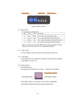
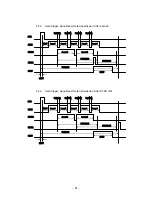
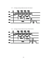
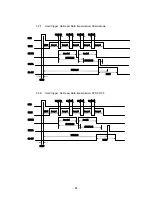
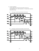
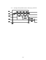
1. Input a trigger signal that is one of 3 types below:
•
Serial
command
•
Digital input (SYNC input)
•
Press the Read button on the membrane switch
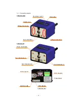
The LED-B (SYNC) turns on (green) and the reader start reading.
2. Result of reading
(1) Good Read
•
1 short beep
•
Symbol’s data will be sent through the interface (RS232C, LAN).
•
Digital output “GO” is ON.
•
LED-C (GO) turns on (green).
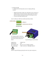
Note: The activated period of “GO” and the monitor LED-C are configurable
through serial commands.
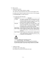
(2) No Read
•
No
beep
•
Error code will be sent through the interface (RS232C, LAN).
•
Digital output “NG” is ON.
•
LED-D (NG) turns on (red).
Note: The activated period of “NG” and the monitor LED-D are configurable
through serial commands.
Summary of Contents for TFIR-31LAN series
Page 2: ...Update Information Edition Date Update Contents 1st edition 2012 06 13 New release...
Page 3: ...1...
Page 89: ...87 7 14 Table of Character code...
Page 91: ...89...
Page 101: ...99 Memorandom...
Page 102: ...100 Memorandom...
Page 103: ...101 Memorandom...
Page 104: ......

