background image


- 68 -


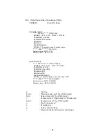
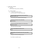
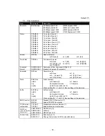
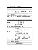
Local Port number (TCP server port number of the reader) 


Remote IP address (IP address of the connected PC) 


Remote Port number (Port number of the connected PC) 


TCP/IP server socket status 


?version


Local IP address (IP address of the reader) 


Local Port number (TCP server port number of the reader) 

 System 

version 

 Decoder 

version 

 Model 

name 


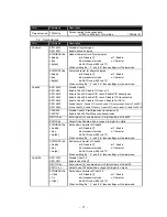
discon<TCP/IP port number>


Shut down TCP/IP connection of the specified port number. 


* <TCP/IP port number> should be set in decimal. 

e.g.) discon 27110 


The command “?who”, “?netstat”, “?version” and “discon” can be used in UDP/IP 

connections. 


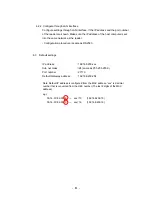
6.8  Initialize LAN settings 

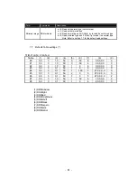
If the LAN settings are unknown, the following steps will reset the LAN settings: 

- Turn off power of the reader. 

- Turn on power pressing the “Teach” button on membrane switch. 


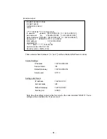
Default settings 

IP address   

: 192.168.209.xxx 

Sub net mask 

: /24 

Default Gateway 

: 192.168.209.254 

Port 

  : 

27110 


Summary of Contents for TFIR-31LAN series

Page 1: ...Operation Manual TFIR 31LAN series TFIR 31LAN 31LAN H Fixed mount 1D 2D Image Reader 2012 06 13 1st Edition...

Page 2: ...Update Information Edition Date Update Contents 1st edition 2012 06 13 New release...

Page 3: ...1...

Page 4: ...uring normal use please document it carefully to ensure our support team can accurately reproduce the situation The contents of this manual may change without notice Please check our website for the m...

Page 5: ...ury or death associated with unintended authorized use Handle with care DATA BACKUP This product has a memory backup function This backup data restoration cannot be guaranteed if repair reconstruction...

Page 6: ...ture outside the rating Exposed to relative humidity outside the rating Exposed to rapid temperature fluctuations causing condensation Exposed to direct sunlight or near heaters Exposed to direct vibr...

Page 7: ...e reader check that there has been no damage to the packaging Check that the box includes the items listed below If any items are missing or damaged please contact your local sales representative Incl...

Page 8: ...PORT SELECTION RS232C LAN 19 2 4 CONFIGURATION 19 2 5 TRANSFER IMAGE DATA 19 3 OPERATION MODE 20 3 1 SINGLE READING MODE 21 3 2 READING TIMEOUT MODE 23 3 3 EXTERNAL TRIGGER MODE 27 3 4 CONTINUOUS REA...

Page 9: ...C LAN 69 7 1 COMMUNICATION 70 7 2 SYMBOLOGIES 71 7 3 SYMBOL READING 79 7 4 CAMERA CONTROL 1 FOR FIXED GAIN AND AUTOMATIC GAIN CONTROL MODE 81 7 5 CAMERA CONTROL 2 FOR TABLE MODE 82 7 6 CAMERA CONTROL...

Page 10: ...ER DOES NOT START UP OR CANNOT COMMUNICATE WITH A PC 96 10 2 SYMBOL CANNOT BE DECODED 97 10 3 FAIL TO COMMUNICATE THROUGH TCP IP PROTOCOL 98 10 4 AFTER GOOD READ THE READER EMITS 7 SHORT BEEPS A FEW S...

Page 11: ...rosoft Corporation in the United States or other countries z If the image reader does not work in your system environment with Windows PC please contact your local sales representative 3 The TFIR 31LA...

Page 12: ...rce and diffused illumination source TFIR 31LAN Spot illumination source A and spot illumination source B 1 1 Supported Symbologies 1D bar codes Code39 Code128 EAN128 Codabar ITF interleaved 2 of 5 JA...

Page 13: ...nector MAC address Interface cable LAN connector Product label Diffused illumination Diffused illumination Membrane switch Spot illumination Rear panel Camera lens TFIR 31LAN TFIR 31LAN H Spot illumin...

Page 14: ...N connector LAN interface LAN Send and receive data to from host device LAN cable is not included LAN indicator Green On when the LAN connection is established LAN indicator Red Blinking when data is...

Page 15: ...when the symbol is not decoded successfully And also this signal is OFF when starting the next reading Ready signal Ready signal is ON when the reader is ready for reading Busy 1 signal Busy 1 signal...

Page 16: ...tab Note The DIO plug is attached to the DIO socket Factory default Applicable wire AWG 20 to 26 Stripping length 8mm DIO connector socket MC 0 5 5 G 2 5 PHOENIX CONTACT DIO connector plug FK MC 0 5 5...

Page 17: ...lied from through the optional AC adapter 1 2 7 Internal illumination source TFIR 31LAN H The spot type light source illuminates the central part of the image reader s field of view The diffused type...

Page 18: ...16 1 2 9 Camera and pointer illumination Two pointer illuminations aiming beam indicate the central area of the image reader s field of view Symbol Pointer illumination Field of view...

Page 19: ...able to the reader The LED A Ready turns on red if the reader is correctly powered A combination of 2 long beeps and 3 short beeps will indicate that the reader has started up correctly Block diagram...

Page 20: ...Good Read 1 short beep Symbol s data will be sent through the interface RS232C LAN Digital output GO is ON LED C GO turns on green Note The activated period of GO and the monitor LED C are configurabl...

Page 21: ...until the data on the interfaces is cleared To avoid this situation turn off RSCS control RSCS 0 or establish both connections correctly 2 4 Configuration TFIR 31LAN can be configured by sending the s...

Page 22: ...reader reads continuously while the SYNC input is active Autosense Mode SYMCMODE 3 The reader detects a symbol coming into the field of view automatically and starts reading it Read includes capturin...

Page 23: ...time the GO signal is asserted NGOUT The length of time the NG signal is asserted SERIAL The time the data is output through the serial interface MAXIMG The maximum number of images in the buffer WAI...

Page 24: ...ta transmission After decode 3 1 3 Hard trigger No Read Data transmission After decode DELAY SYNC IMAGE DECODE SERIAL NGOUT NGOUT CHATT DECODELIM decode1 image1 DELAY SYNC IMAGE DECODE SERIAL GOOUT GO...

Page 25: ...MG is set to a number greater than 1 The reader tries to decode the image while capturing 3 2 1 Soft trigger Good Read Data transmission After decode 3 2 2 Soft trigger Good Read Data transmission Aft...

Page 26: ...F DELAY SYNC IMAGE DECODE SERIAL GOOUT GOOUT CHATT DECODELIM DECODELIM WAITIMG WAITIMG WAITIMG WAITIMG decode1 decode2 image1 image2 image3 image4 image1 TOTALLIM DELAY SYNC IMAGE DECODE SERIAL GOOUT...

Page 27: ...C OFF SYNC DELAY IMAGE WAITIMG WAITIMG WAITIMG WAITIMG image1 image2 image3 image4 image1 DECODE DECODELIM DECODELIM decode1 decode2 SERIAL NGOUT NGOUT TOTALLIM SYNC WAITIMG WAITIMG WAITIMG WAITIMG DE...

Page 28: ...TT DELAY IMAGE image1 image2 image3 image4 image1 SERIAL SYNC WAITIMG WAITIMG WAITIMG WAITIMG DECODE DECODELIM DECODELIM decode1 dcode2 NG OUT NGOUT TOTALLIM DELAY SYNC IMAGE WAITIMG WAITIMG WAITIMG W...

Page 29: ...Good Read Data transmission After decode 3 3 2 Hard trigger Good Read Data transmission After SYNC OFF DELAY SYNC IMAGE DECODE SERIAL GO OUT GOOUT CHATT DECODELIM DECODELIM WAITIMG WAITIMG WAITIMG WAI...

Page 30: ...d trigger No Read Data transmission After decode or SYNC OFF DELAY SYNC IMAGE DECODE SERIAL NGOUT NGOUT CHATT DECODELIM DECODELIM WAITIMG WAITIMG WAITIMG WAITIMG decode1 decode2 image1 image2 image3 i...

Page 31: ...rt reading send the serial command TEST 1 to the reader To exit the Test Mode send the serial command TEST 0 to the reader With Test Mode the reader will output an asterisk to the host for each 10 of...

Page 32: ...l attempt to decode the image stored in memory location 2 The decoding is attempted during the interval between capturing images When the buffer memory reaches the final location the next image will b...

Page 33: ...tal brightness or the motion of an object the TFIR 31LAN begins capturing images in an attempt to decode a symbol This function is suitable for reading a symbol printed on a document in the case of in...

Page 34: ...it starts reading the symbol on the object 4 In case of Good Read the reader will send the decoded data and turn on LED C green and GO signal digital output 5 In case of No Read the reader will send t...

Page 35: ...symbols in Autosense Mode Please remove the object from the field of view and wait until the pointer starts blinking and then place it in again step 1 in section 3 7 1 3 7 3 Serial command Please refe...

Page 36: ...eader is highly sensitive to detect motion change of the object 3 7 8 Double read prevention LFVERIFY When the reader reads the same symbol again within the specified time the second read will be igno...

Page 37: ...age out 3 OK NG 4 OK 5 NG SYNCMODE 1 0 normal 1 time out 2 hard trig TEST 0 0 normal 1 test mode TMN 10 TEST 1 n times 10 1000 DECODELIM 500 100 10000 step10 TOTALLIM 5000 100 30000 DTTX 0 0 non 1 add...

Page 38: ...ecode area is used to specify the the area of the image to be decoded Shown below Smaller decode area can lead to a faster decoding speed but smaller areas may make it difficult to position the symbol...

Page 39: ...ation B 1 Enable spot illumination B b 0 Disable spot illumination A 1 Enable spot illumination A 4 Illumination Intensity DDMbrightness DDMbrightness a a 0 to 50 Adjust the illumination intensity fro...

Page 40: ...ark for optimal decoding DDMblack a a 127 to 127 4 1 6 Image preprocessing 8 Image preprocessing DDMpreproc Image processing filters are available for difficult to decode symbols Under certain circums...

Page 41: ...ode the reader uses only Table 0 settings The settings in Table 0 will not be changed automatically Automatic Gain control mode AGC E In Automatic Gain Control Mode the reader uses only Table 0 settin...

Page 42: ...There are eight tables available numbered from 1 to 8 The ENABLEDDMTBL command determines the number of tables to be used when the reader is attempting to decode a symbol This mode is most effective...

Page 43: ...ly Table 1 is enabled Table 2 through 8 will not be used As the result Table 1 is always used every reading The following shows the structure of the Table Each table has 9 types of parameters 1 Decode...

Page 44: ...l command below to assign the table number to be edited EDITDDMTBL a a 1 to 8 2 Configure the parameters Refer to section 4 1 Configuration parameters for detailed information 3 Edit another table Rep...

Page 45: ...ode 2 PREM 0 CR Preset Mode 0 Preset Mode is disabled PREM 1 CR Preset Mode 1 Preset data is the first decoded one after power up PREM 2 CR Preset Mode 2 Preset data is registered in advance To disabl...

Page 46: ...settings to internal flash memory e g 1 Example 1 Only 12345 is valid 12345 match 1234 mismatch 123456 mismatch 012345 mismatch PREM 2 CR SET PRED12345 CR Set the preset data data is 12345 SET PREN5 C...

Page 47: ...digits to 6th digits are ALFA 00ALFA1234 match AAALFAAAAA match 00ALFA12345 mismatch 0ALFA12345 mismatch PREM 2 CR SET PRED ALFA CR Set the preset data data is ALFA and is mask SET PREN10 CR Set the n...

Page 48: ...9 Output format PREM a 0 non 1 power on 2 saved CR PRESET LENGTH b CR DATA HEX CR XX XX XX XX XX XX XX XX XX XX CR XX XX XX XX XX XX XX XX XX XX CR XX XX XX XX CR DATA ASCII CR xxxxxxxxxxxxxxxxxxxxxxx...

Page 49: ...by sending the serial command CHKBCR a b a is for RS232C interface and b is for LAN interface e g 1 CHKBCR 0 1 Added only for RS232C CHKBCR 1 1 Added for both interface CHKBCR 1 Same as CHKBCR 1 1 CH...

Page 50: ...ded in case of No Read Output format aa bbbbbms aa Number of images bbbbb Total time ms 5 2 6 Contrast Information Add the Contrast Information of the last decoded image 1 Good Read Calculate contrast...

Page 51: ...ld be 100 If the symbol is not decodable the Quality Information will not be added Output format QT ddd 8 bytes ddd Quality 000 to 100 5 2 8 Symbol Coordinates The positional data of the symbol in the...

Page 52: ...455 086 386 270 198 199 Output format Header Data A1 A2 A3 A4 Terminator A1 A4 abbb accc a or b x 0 to 999 c y 0 to 999 Barycentric coordinates 376 239 375 239 376 240 375 240 Origin 000 000 Field of...

Page 53: ...1 A2 A3 A4 Terminator B The center of a symbol B A1 A4 abbb accc a or b x 0 to 999 c y 0 to 999 5 2 9 Table Number Example output 100000000990703 ddmtbl 3 Output format Header Data ddmtbl a Terminator...

Page 54: ...n is enabled IMGFULL 1 CR After images are stored in buffer from 1 through 4 latest images will be overwritten in buffer 4 To delete the image send the IMGCLEAR command to the reader 5 3 1 Select type...

Page 55: ...itten in buffer 4 5 3 4 Preparation for transmitting the saved image Using TECT for TFIR 317x software allows the download of the saved image that has been completed the preparation of transmission IM...

Page 56: ...TFIR 31LAN CR IMODE a PX b PY c WX d WY e CR CAPMODE f g h i CR DECMODE j k l m n CR IMGSAVE o CR IMGFULL p CR SAVEDIMGNUM q CR IMGSEL r 0 captured image 1 decoded image CR END TFIR 31LAN CR System ve...

Page 57: ...st 20 bytes 4 Error log Error log 5 Read score OK NG SYNC 6 No Read Record only if the number of read symbol less than LABELS 7 SYNC on off External trigger 8 Received data Received data except serial...

Page 58: ...8 534169 11 Successed Initialize TCP 8 534934 11 Successed Initialize UDP Example output of Log trace PRNTLOG 7 935205 11 TFIR 31LAN M21C V1 0a M21A V1 0a 7 935316 11 Build Version V1 0a 01 7 947346 1...

Page 59: ...command via TCP IP UDP Cmd The command via UDP 3 Decoded data Example QR Code Data is QR CODE123 data size is 10 bytes 23 385679 3 QR CODE123 QR Code 127ms 4 Error log e g 1 Communication failure wit...

Page 60: ...cvData Data via TCP IP UDP RecvData Data via UDP 9 Camera settings 17 580325 9 SHUTT 4 GCV 5 LIGHT 3 17 580367 9 brightness 25 led 1 0 black 0 10 Membrane switch Read button 138 373294 10 Sync Membran...

Page 61: ...P address 9 708538 11 IP address 192 168 209 032 Sub net mask 9 708607 11 Sub net mask 255 255 255 000 Default gateway 9 708662 11 Default gateway 192 168 209 254 MAC address 9 708715 11 MAC address 0...

Page 62: ...22 Service port 148 039387 13 Service port 27110 5 4 2 Output trace 12 Output data e g 1 Good Read data 1234567890ABCDEFGHIJKLMNOPQRSTUVWXYZ No Read Terminator setting is CR LF PRNTOUTPUT 525 949514 1...

Page 63: ...by state after a certain period 2 To start the setup function press the Read button once while LED A is blinking The reader will start tuning procedure 3 After the procedure the reader will indicate t...

Page 64: ...and below The subnet mask can be omitted 24 will be assigned Configure the port number by the command below Configure the default gateway address by the command below Set the same network as IP addres...

Page 65: ...der Configuration procedure is same as RS232C 6 3 Default settings IP address 192 168 209 xxx Sub net mask 24 same as 255 255 255 0 Port number 27110 Default Gateway address 192 168 209 254 Note Defau...

Page 66: ...24 USBCOMPAT 0 END TFIR 31LAN System version M21C V1 0a Decode version M21A V1 0a These values shown between and will be activated after Power on reset Current Settings IP address 192 168 209 036 Sub...

Page 67: ...own 1 Set IP address of the host into the same network as the reader 2 Set the UDP settings Remote IP address TFIR 31LAN for broadcasting e g If remote IP address is 192 168 209 255 all TFIR 31LAN uni...

Page 68: ...et to any value Only one client can be connected at a time The reader will disconnect in the following situations Receive close request from the client Detect transmission error In the following cases...

Page 69: ...s in dotted notation Set default gateway address of the reader IPPORT TCP IP port number decimal Set TCP IP port number of the reader TCPCS a a 0 Disable a 1 Enable Set the function of data arrival co...

Page 70: ...l name discon TCP IP port number Shut down TCP IP connection of the specified port number TCP IP port number should be set in decimal e g discon 27110 The command who netstat version and discon can be...

Page 71: ...eader Serial command Terminator To add header and terminator characters to a serial command send the command CMDFORM 1 The header and terminator characters set by HEAD and TERM command will be applied...

Page 72: ...mmand CR or Command CR LF Format CMDFORM 1 Header Command Terminator Separator SEPA a Character code a 0 None a 1 a 2 Comma a 3 FS 1C hex a 4 GS 1D hex a 5 SP 20 hex Prefix PREFIX a Prefix character a...

Page 73: ...e C D transmission Enable Full ASCII SET AM6 Enable Code39 Enable C D check Disable C D transmission Enable Full ASCII C39SS 0 Disable Code39 Start Stop code transmission C39SS 1 Enable Code39 Start S...

Page 74: ...de c Character ea dd dd ASCII code 00 to 1F When omitting bb c and dd those settings will be remained Codabar SET FM0 Disable Codabar SET FM1 Enable Codabar Disable C D check SET FM2 Enable Codabar En...

Page 75: ...Enable Ga c bb Hexadecimal code c Character Ga dd dd ASCII code 00 to 1F When omitting bb c and dd those settings will be remained SYMFOOT Ga Set footer character of Code93 Ga bb a 0 Disable a 1 Enabl...

Page 76: ...e only for square rectangle shaped and normal DataMatrix SET dM6 Enable only for square rectangle shaped and inverse DataMatrix SET dM7 Enable all types of DataMatrix DIGIT db c Set minimum b and maxi...

Page 77: ...Character Ua dd dd ASCII code 00 to 1F When omitting bb c and dd those settings will be remained SYMFOOT Ua Set footer character of MaxiCode Ua bb a 0 Disable a 1 Enable Ua c bb Hexadecimal code c Cha...

Page 78: ...IZE a Set the size of QR Code relative to field of view a 0 Normal a 1 Small RSS SET eM00 RSS Disable RSS SET eM01 RSS Enable RSS Expanded SET eM02 RSS Enable RSS Expanded Stacked SET eM04 RSS Enable...

Page 79: ...o 1F When omitting bb c and dd those settings will be remained SYMFOOT Set footer character of Composite ea bb CC a 0 Disable a 1 Enable ea c CC bb Hexadecimal code c Character ea dd CC dd ASCII code...

Page 80: ...b a 0 Disable a 1 Enable za c bb Hexadecimal code c Character za dd dd ASCII code 00 to 1F When omitting bb c and dd those settings will be remained Multi Labels LABELS a Number of labels a 1 to 4 a 1...

Page 81: ...0 Disable aaaa XXXX except 0000 Add ID number Warning Information CHKBCR a b a 0 Disable addiction for RS232C a 1 Enable addiction for RS232C b 0 Disable addiction for LAN b 1 Enable addiction for LAN...

Page 82: ...ms MAXIMG a Number of captured images a 1 to 4 a 1 Cycle Buffer Function WAITIMG a Capture interval of time when MAXIMG is greater than 1 a 0 to 1000 ms a 100 ms Pointer POINTER a Pointer control a 0...

Page 83: ...0 to 50 0 Off 50 Brightest Internal Illumination CAMled c b Set the type of internal illumination source TFIR 31LAN H Both type spot and diffused can be used in reading c 0 Disable spot type c 1 Enab...

Page 84: ...ng Illumination Intensity DDMbrightness a Brightness level is set in 50 steps a 0 to 50 0 Off 50 Brightest Internal Illumination DDMled c b Set the type of internal illumination source TFIR 31LAN H Bo...

Page 85: ...ault table settings 7 7 Default Table settings TFIR 31LAN 31LAN H Table 1 2 3 4 5 6 7 8 9 0 0 0 3 1 0 50 0 50 6 0 0 0 0 0 0 1 0 0 3 1 0 50 0 50 6 0 0 0 0 0 0 2 0 0 3 1 0 50 1 0 6 0 0 0 0 0 0 3 0 0 3 0...

Page 86: ...le values from the image and makes them white Then stretches the contrast to fill the entire 256 gray scale values 24 Cont H25cut Removes the brightest 25 of the gray scale values from the image and m...

Page 87: ...r Autosense mode IMG Status Transmission for Image ouput and Image save ddmtbl Status Transmission for Table settings 7 11 Image output Image save Term Command Description Select type of image IMGSEL...

Page 88: ...on Get the model name and firmware version LAN settings discon aaaaa Disconnect the specified TCP IP connection forcibly aaaaa Port number Decimal 7 13 General Operation Term Command Description Initi...

Page 89: ...87 7 14 Table of Character code...

Page 90: ...H 5Vdc 10 Approx 0 8A Serial interface RS232C 1200 to 115 2k bps LAN interface Ethernet 10Base T Data format ASCII Image sensor 1 3 inch monochrome CMOS Image format WVGA 752x480 Digital input 1 opto...

Page 91: ...89...

Page 92: ...90 8 1 Dimensions 55 50 63 5 17 5 35 45 10 Teach Read D C B A Units mm Mounting threaded hole 2 M3 tapped holes depth 5mm...

Page 93: ...locks Note The above is listed realative to the reader TFIR 31LAN end of the INPUT OUTPUT transactions with the host DC power Jack optional EIAJ Pin Name Function Direction 1 NC OPEN 2 SD Transmit dat...

Page 94: ...nal block opto isolated digital input output Internal Circuit Diagram GO 4 COM SYNC SYNC NG 1 2 3 5 Pin Name Function Direction 1 SYNC Sync input Input 2 SYNC Sync input Input 3 GO OK output Output 4...

Page 95: ...0 10 20 30 10 20 30 20 26 32 37 43 0 10 20 10 20 0 50 40 60 70 30 13 16 20 24 27 Read Teach D C B A Units mm Symbologies Cell size Near Far 0 125 36 54 0 167 32 58 Data Matrix 0 25 28 68 0 125 36 54...

Page 96: ...10 20 30 10 20 30 40 50 40 50 0 50 40 60 70 30 80 90 100 110 120 130 140 150 55 50 35 17 5 Read Teach D C B A Units mm Symbologies Cell size Near Far 0 125 50 74 0 167 43 85 0 25 40 95 0 33 30 115 0...

Page 97: ...GO and NG No Product name Model name Note 1 AC adapter 5Vdc KSAC0500160W1UV 1 Optional 2 LAN cable cross over Not specified greater than category 3 Optional Note While a LAN cable is optional the set...

Page 98: ...gs The reader port is set by the serial command COMFROM If the port is set to RS232C COMFROM 0 both way LAN data communication between the reader and the host would not work Is the format of serial co...

Page 99: ...ust be within the specified reading distance If the code is damaged or the print quality is low it may not be decodable even if the reading depth requirements have been met Is the reading window clean...

Page 100: ...accidental unplug plugin of the LAN cable while the reader is in working mode Retry the connection process after disconnection To recover the connection send the command discon through RS232C interfac...

Page 101: ...99 Memorandom...

Page 102: ...100 Memorandom...

Page 103: ...101 Memorandom...

Page 104: ......

Reviews: