background image

T: +1-613-545-0466       F: +1-613-542-8029       www.mrel.com

17

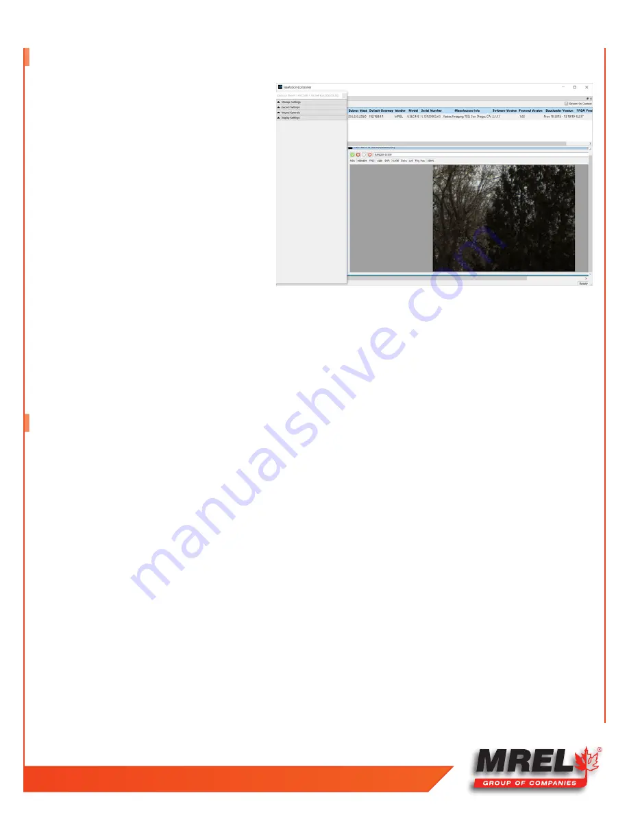
4.6 FasMotion Application Window

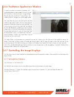
As soon as a camera is connected via FasMotion, two 
additional dockable windows appear. To the left, you see 
the Control Panel, which has five tabs: Storage Settings, 
Record Settings, Record Controls, Display Settings, and 
Autosave Setup. To the Right, you see the image window.

The Control Panel may remain docked to the left side of the 
FasMotion application window or be moved outside of the 
application window to any location on your desktop. If you 
use two displays, you may wish to move the Control panel 
to your extended desktop in order to give yourself a larger 
image window. The Control Panel detaches by clicking on 
the gray border at the top. To return the Control Panel back 
to the application window, just double-click on that same 
border. FasMotion...Window...tick Control Panel if you can 
not see the control window on left.

The Image Window may be detached and moved and/or resized, but it always stays within the bounds of the application window. To 
detach it, click on the “minimize” button in the upper right corner (circled in red). To restore the window, click on the “maximize” button 
(in the same location). The Video Controls pane will appear at the bottom of the Application Window whenever a video is open for 
review. This is another detachable pane that may be moved outside the application window by grabbing its top border. Double click on 
the same border to restore it to its original position.

4.7 Controlling the Image Displays

The View Menu contains zoom controls that are replicated at the top of the application window. These control the size and shape of the 
Image Window.

4.7.1 Setting Default Gamma:

User Preferences is in the Camera menu.

The Default Gamma setting is used to set the default output Gamma for displayed and saved images.

The default Gamma is 1.0 (linear). Many laptop computer displays have a Gamma of 1.0, while most larger flat panel LCD
monitors have a Gamma of 2.2.

Summary of Contents for Blaster's Ranger II Lt

Page 1: ...MREL GROUP OF COMPANIES LIMITED 1555 Sydenham Road Kingston Ontario K7L 4V4 Canada T 1 613 545 0466 F 1 613 542 8029 E blasting mrel com www mrel com Operations Manual Edition 1 1 Lt ...

Page 2: ...ocumentation are sold as is without warranty as to their performance merchantability or fitness for any particular purpose The Customer assumes the entire risk as to the results and performance of the product MREL is committed to product innovation accordingly product may undergo specification improvements without notice Copyright 2016 MREL Group of Companies Limited Blaster s Ranger II Lt High Sp...

Page 3: ...ProAnalyst Introductory Edition Software 8 Chapter 3 Getting Started 9 3 1 Introduction 10 3 2 Powering Up 10 3 2 1 Attaching the External DC Power Supply 10 3 3 Camera Setup 10 3 3 1 Blaster s Ranger II Lt Setup 11 3 3 2 Mount the C Mount Zoom Lens to the camera 11 3 3 3 Blaster s Ranger II Lt I O Cable and Trigger Switch Cable 11 3 3 4 DC Power Connection 12 Chapter 4 FasMotion 13 4 1 Install Fa...

Page 4: ...2 To Load a Saved Configuration 21 4 12 3 To Load the Factory Configuration 21 4 13 Reboot and Power Down 21 4 14 Camera Information 22 Chapter 5 Recording 23 5 1 Long Record and Standard Modes 24 5 1 1 Switching from Standard mode to Long Record Mode 24 5 1 2 Switching Back to Standard Mode 24 5 2 Setting Frame Rate and Resolution 24 5 2 1 To set the Resolution of the Camera 25 5 2 2 To set the F...

Page 5: ...splay 35 5 12 8 Zooming in on the Timeline 35 5 12 9 To Zoom In 35 5 12 10 Viewing Per Frame Metadata in FasMotion 35 5 12 11 To View Per Frame Metadata 35 5 13 Image Processing 36 5 13 1 Image Processing Pipeline 36 5 13 2 User Control of Image Processor 37 5 14 Custom Color Correction 37 5 14 1 Using RGB Gain Controls 38 5 15 Saving Images to Mass Storage 38 5 16 Transfers Batch Transfers and Co...

Page 6: ...2 Example Demonstration File Explanation Mining Example 56 8 2 1 Image Processing 57 8 2 2 Multi Plane Calibration 57 8 2 3 Display Layers 58 8 2 4 Notes 58 8 2 5 Annotations 58 8 2 6 Feature Tracking 58 8 2 7 Under the Tracking box 60 8 2 8 Save All Toolkits 60 8 3 Excel Spreadsheet Mining_Demo xls 60 8 3 1 Explanation of the Unshaded Cells 61 8 4 Example Demonstration File Explanation Disrupter ...

Page 7: ...T 1 613 545 0466 F 1 613 542 8029 www mrel com 1 Chapter 1 Introduction ...

Page 8: ...ion of the high speed digital camera blasters are now able to play pause and analyze a blast in perfect clarity as soon as the event has occurred It is the goal of the Blaster s Ranger II Lt High Speed Digital Camera to put the simplicity of digital video editing and analysis into your hands without sacrificing the resolution that has typically accompanied high speed film cameras of the past One o...

Page 9: ... delay times and the casting range of the muck With proper preparation and care during the set up operation and analysis considerable information may be obtained which can suggest where improvements may be required in the blasting operation In addition the video provides a permanent record of the event and allows any changes made between blasts to be easily and accurately analyzed Before the intro...

Page 10: ...4 Blaster s Ranger II Lt Operations Manual Edition 1 1 Lt ...

Page 11: ...T 1 613 545 0466 F 1 613 542 8029 www mrel com 5 Chapter 2 Hardware ...

Page 12: ...r II Lt to be quickly mounted onto the Tripod s Grip Action Ball Head shown in Section 2 2 3 The Mounting Adapter and the Tripod s Grip Action Ball Head are part of the Blaster s Ranger II Lt Accessories Package The Blaster s Ranger II Lt is equipped to accept any standard C Mount or F Mount Lens depending on the resolution of the camera 2 1 Blaster s Ranger II Lt High Speed Digital Video Camera T...

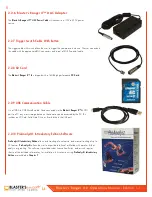
Page 13: ...of 1280X1024 and shown to the right Zoom lens 12 5 75 mm is for the model of resolution of 800X600 2 2 3 Tripod and Grip ball Head This is an all aluminum Tripod with a 3 8 mounting screw This Tripod is designed to support the Grip Action Ball Head with the Blaster s Ranger II Lt attached This is the only item that does not fit inside the Protective Carry Case 2 2 4 Blaster s Ranger II Lt DC Power...

Page 14: ...ation Cable It is a USB A to USB Micro B cable Once connected via the Blaster s Ranger II Lt OTG port to a PC any mass storage device on the camera can be accessed by the PC This includes an SD Card Solid State Drive or thumb drive in the USB port 2 2 10 ProAnalyst Introductory Edition Software ProAnalyst Introductory Edition allows auto tracking of one feature and manual tracking of up to 32 feat...

Page 15: ...T 1 613 545 0466 F 1 613 542 8029 www mrel com 9 Chapter 3 Getting Started ...

Page 16: ...Blinking Green Operating 15 5 Amber Charging 15 5 Blinking Amber Operating 5 Blinking Red Charging 5 Blinking Red Operating Not Installed Blue 3 3 Camera Setup There are several precautions that must be remembered prior to using the Blaster s Ranger II Lt The suggested procedure for assembly of the system is detailed in the following sections 3 1 Introduction 3 2 Powering Up This chapter provides ...

Page 17: ...oom Lens to the camera If you have the high resolution 1280 X 1024 camera it is a F Mount with a 80 200 mm lens Remove the lens receptacle cover from the camera s F mount This is a cover that is installed at the factory to protect the camera optics and sensor from dust contamination NOTE Whenever threading lenses on or off the camera face the camera lens down so that any contamination on the threa...

Page 18: ...er Connection The camera can be powered by a 12 V AC DC adapter or the external 12V DC battery 3 3 5 Ethernet connection Connect the camera with your laptop a computer or a network switch using one cat5 or cat6 straight through Ethernet cable Figure 4 I O Cable and Trigger ...

Page 19: ...T 1 613 545 0466 F 1 613 542 8029 www mrel com 13 Chapter 4 FasMotion ...

Page 20: ...nd click on Next 5 The next window gives you the option on creating a shortcut for FasMotion in the directory of your choice Select a directory for a shortcut or click the Do not create shortcuts check box Click on Install to continue 6 FasMotion will now be installed on the PC A window with a progress bar will appear and inform you when the install is complete 7 The final install window gives you...

Page 21: ...I Lt 3 Watch the LEDs on the camera s RJ 45 connector When the camera connects to the PC or local network the green LED will begin to blink in a pattern depending on connection speed 4 Start the FasMotion software application 5 Select a camera from the Found Cameras list in FasMotion Double click to open Note It is possible to use a wireless adapter on your PC but it is not recommended because of ...

Page 22: ... mask and gateway 4 Type in the password if needed and then click on OK The dialog will close 5 If you selected DHCP you can re open the WiFi configuration dialog after a few minutes and you will see the assigned IP address for the camera 4 5 2 WiFi Setup for an Ad Hoc Network 1 Select WiFi Config from the Configuration Menu 2 Click on the Manual button This will allow you to edit the name in the ...

Page 23: ...control window on left The Image Window may be detached and moved and or resized but it always stays within the bounds of the application window To detach it click on the minimize button in the upper right corner circled in red To restore the window click on the maximize button in the same location The Video Controls pane will appear at the bottom of the Application Window whenever a video is open...

Page 24: ... may be used to temporarily start and stop the video stream 4 7 3 Setting up the HDMI display The Blaster s Ranger II Lt has an HDMI output that can be used for displaying both live and recorded images The HDMI port is located on the side of the camera between the Power and External I O connectors To enable the HDMI output click on the HDMI button on the Display Settings Tab and select the resolut...

Page 25: ... the camera name into the browser s Location bar 2 A camera control application within the camera does the rest A control menu will appear in your browser that will give a live camera view and complete control over the camera operation Details on use of the camera s web browser appear in Chapter 6 of this manual Note The Web Application is useful for setting up and controlling the camera but it do...

Page 26: ...io button in the Storage Settings dialog and click on Format When formatting the SSD on a Blaster s Ranger II Lt and many Blaster s Ranger II Lt cameras you may be given an option of Sanitizing the drive Sanitization is a low level process that securely erases all data and renews the SSD for optimal performance 4 11 3 Formatting SD Cards and USB drives Formatting SD Cards and USB drives is the eas...

Page 27: ... saved cfg files and select the Configuration you would like to load 4 12 3 To Load the Factory Configuration Click on Factory Config in the Camera Menu This will load the factory default settings for the camera Note This is not a routine operation as it rewrites your camera configuration Always power cycle the camera after loading Factory Configs 4 13 Reboot and Power Down The camera may be Power...

Page 28: ...dow click on the Find Cameras icon in FasMotion The information fields will populate as soon as you select a camera from the Found Cameras list Information Included MAC address IP address Subnet Mask Default Gateway Vendor Model Serial Number Main Board Rev Manufacture Info location Software Version GigE Protocol Version Bootloader Version FPGA Version Sensor Version ...

Page 29: ...T 1 613 545 0466 F 1 613 542 8029 www mrel com 23 Chapter 5 Recording ...

Page 30: ... Recording Mode 5 1 2 Switching Back to Standard Mode 1 With the camera in Live go to Configuration Preferences 2 The User Preferences dialog will open De select the Long Recording Mode check box 3 Click on OK to accept the changes The Mode Change dialog will appear again but this time the text informs you that you will need to format the SSD before you will be able to write to it in Burst Mode 4 ...

Page 31: ...keyboard arrow keys Often the best way to do this is by dragging it with the mouse until it is close to the value you want then using the arrow keys to zero in on the exact value 5 2 2 To set the Frame Rate of the Camera Either edit the number in the Frame Rate edit box or move the Frame Rate slider to the desired position using the mouse and arrow keys 5 2 3 Offset Control Most of the time to mak...

Page 32: ...itched on for a short time and are not available for camera set up The exposure for Low Light Mode is much longer than would be possible for a high frame rate The default shutter speed for Low Light mode is 41 666ms which is the 1X shutter speed for 24fps The shutter speed for Low Light may be adjusted via FasMotion by checking the Low Light box and moving the slider or editing the Low Light edit ...

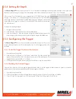
Page 33: ...its presents brighter images with added noise 5 5 Configuring the Trigger The Blaster s Ranger II Lt uses a fixed selectable circular buffer to record into The session length is determined by the user This section explains how to set the trigger position within the buffer 5 5 1 To Set the Trigger Position in the Camera 1 Open the Record Controls Tab 2 Select either the Use Percent or Use Frames ra...

Page 34: ...se follow the shutter timing Selecting Duty Cycle allows you to select the of time the Sync Out pulse is True This may be used in conjunction with polarity choices to establish the phase relationship between devices For timing diagrams and a more detailed description of how these signals may be used for camera synchronization please refer to 5 Synchronizing Cameras on page 50 5 6 3 Enable Arm In A...

Page 35: ... following Pixel FPN is a per pixel image correction that is done in the Blaster s Ranger II Lt s image processor engine It provides the cleanest images available This is the setting that is most highly recommended Column FPN is an image correction done on the Blaster s Ranger II Lt s sensor It does not do as good a job cleaning up the images as Pixel FPN FPN Off means that there is no noise corre...

Page 36: ... the Video Review Tab will open exposing the Save dialog and the Video Control Playback pane will open 5 9 Autosave The Blaster s Ranger II Lt may be used to capture many consecutive events Using Autosave this can be done unattended that is the camera may be left at a location to automatically Trigger Save captured imagery and then re Arm itself indefinitely constrained only by the mass storage sp...

Page 37: ...l usually find that the camera has saved one or more partition before you get to the last one Depending on the session size the speed of the media and the interval between events you will often find that you will be able to keep recording clips at will until the space in the save media is exhausted 5 10 1 Entering FasFire via FasMotion The camera will operate in FasFire mode whenever there are at ...

Page 38: ...ndard Basic mode Note If you wish to stop recording before all of the post Trigger frames are recorded you may cancel the recording by clicking the Arm button then select Yes to retain the current session in the Cancel Record dialog The basic performance specifications vary depending on model but generally Long Record allows for much longer recordings at slightly slower frame rates than Standard m...

Page 39: ... image brightness contrast gamma bit depth color etc Save video to a mass storage device Load a CAP file from SSD to memory for Review 5 12 1 Searching for Interesting Parts Very often the first thing you will wish to do when reviewing a clip is to scrub through it using the playback slider looking for the most interesting moments 1 Click on the Pause Play button Only necessary if you have already...

Page 40: ...ample in Absolute mode if you have a recording that begins at 6 56 am and ends at 7 01 am the Hour Minute and second fields will be active In Relative Mode only the Minute and second fields will be active 5 12 5 Jumping to Markers Blaster s Ranger II Lt cameras have six LVTTL I O ports that may be used for camera control or as event marker inputs or some combination of the two Note that the signal...

Page 41: ...g the task of finding specific events in the video much easier 5 12 9 To Zoom In Double click on the timeline to zoom to 2x A highlight mark will appear over the zoomed area of the Timeline and a Zoomed Playback Line that spans the highlighted area will appear below the Playback Line The highlighted portion of the Timeline may be moved by clicking and dragging it so that any portion of the capture...

Page 42: ...e contact MREL Sync Internal The Sync term can be Internal internal camera clock used for frame timing PPF Sync In pulse used for per frame timing or PPS 1Hz clock input at Sync in used to derive the camera frame timing Time Internal The Time is always set to Internal for the Blaster s Ranger II Lt 5 13 Image Processing 5 13 1 Image Processing Pipeline The Blaster s Ranger II Lt image processing b...

Page 43: ... bit images as they are recorded into the Blaster s Ranger II Lt s high speed internal memory Adjustments made here may be done before and or after the imagery is captured Note All image processing is done using 16 bit math If 8 bits are recorded they will be used as the upper 8 bits of the 16 bit calculations by the image processor The upper 8 bits of the results are then used as an output Simila...

Page 44: ...ass Storage Image sequences may be saved as CAP files proprietary raw format as AVI videos in which one file contains all the frames of the sequence or TIFF JPEG or BMP stacks which are collections of files one file per frame of imagery The file save options change depending on whether 8 bit or 10 bit image data has been written to internal high speed memory Calculating file sizes for TIFF and BMP...

Page 45: ..._2011 10 11_000000 TYPE in the example If AVI files are saved the default file name is 000000 AVI The Use Name and Use Tag options are also valid for AVI files in which case the resulting file names are Blaster s Ranger II Lt 11_000000 AVI or 2011 10 11_000000 AVI etc If the file size exceeds the 4GB limit for 32 bit file systems the Blaster s Ranger II Lt will make a second file for the remainder...

Page 46: ... from the Camera s SSD it is not wise to let the SSD become fragmented by deleting files then recording and saving more to the SSD You may wish to delete files as you save them off in order to keep track or what you have saved but you should reformat the drive before using it again 5 16 2 Convert JPEG or BMP Stacks to AVIs JPEG and BMP stacks will be converted to AVI videos during transfers copy o...

Page 47: ...T 1 613 545 0466 F 1 613 542 8029 www mrel com 41 Chapter 6 Using the Web App ...

Page 48: ...igure below Blaster s Ranger II Lt is connected in Live Mode Notice that the Camera Name is displayed in brackets on the Camera Tab and that the camera s mode of operation in this case Live View is listed there as well The Trigger Button is absent because the camera has not yet been armed The Review Tab is also absent as there is no video to review 6 2 Camera Tab Clicking on the Camera Tab exposes...

Page 49: ... balance between size and quality For larger higher quality images use a higher QFactor For smaller lower quality images and faster refresh rates use a lower QFactor Default Gamma setting is used both to set the default output Gamma for displayed and saved images and to set the Gamma for the LCD display Gamma of 1 0 linear is recommended unless you intend to encode your images with 2 2 Gamma Long ...

Page 50: ...ck on Format 3 Select the format type you wish to use Note Format choices vary depending on media type and camera version 6 3 2 Setting the Session Length Session select the amount of memory to be used for capturing imagery on the Blaster s Ranger II Lt not in Long Recording Mode Session length dictates the number of frames captured as well as the capture time 1 Move the Session Length Adjustment ...

Page 51: ...rrent resolution Clicking on the Autoset button will set the frame rate to that maximum number possible with the current resolution setting 6 4 3 Setting the Shutter Speed Set the shutter speed by moving the slider The minimum shutter speed maximum sensor integration time is limited by the frame rate It is 006ms less than 1 frame time or 1 frame rate 006ms The maximum shutter speed minimum sensor ...

Page 52: ...t The sliders used for Brightness Contrast and Gamma you control over the same range as with the presets in the camera but it is a much finer control The color sliders give you control over the RGB gains It is advisable to use the color sliders with a grey card to get good color balance 1 Frame the camera image on a neutral gray object A gray card piece of white paper white wall etc 2 Turn on the ...

Page 53: ...y Settings Tab The Play buttons which only appear when the mouse cursor is brought over them have the same functions as on FasMotion except that the Cut In and Cut Out points are entered by editing the Clipping Range boxes or by adjusting the slider between them The clipping range is then used as it is on the camera GUI for both playback and while saving to mass storage You may jump to the beginni...

Page 54: ...ition 1 1 Lt 6 Select the destination drive using the SD Card SSD and USB Drive radio buttons 7 Click on Save Partition A Progress Bar will appear beneath the image window showing the download status When finished an information window will appear ...

Page 55: ...T 1 613 545 0466 F 1 613 542 8029 www mrel com 49 Chapter 7 Field Operations ...

Page 56: ...onfirmation of the functioning of explosives primers and accessories Determination of the location time and duration of gas venting Assessment of the locations responsible for flyrock or other projectiles Evaluation of the extent of backbreak Determination of the location time and duration of nitrogen oxide emissions Sensor Fusion Combinatory analysis of video data with VOD data or other sensors a...

Page 57: ...T 1 613 545 0466 F 1 613 542 8029 www mrel com 51 ...

Page 58: ...free face To analyze face velocities the Blaster s Ranger II Lt should be located to the side of the blast parallel with the free face Brightly coloured targets should be used as reference points for measuring distance in the ProAnalyst Introductory Edition Motion Analysis Software when the sequence is being analyzed These markers should be positioned exactly perpendicular to the line of sight of ...

Page 59: ...t Select Ext Trigger Make sure it is Enabled If Disabled click on the Disabled button It will turn green and the text will change to Enabled 6 Frame and focus the scene 7 Press the Arm Button to begin recording pre trigger frames The camera settings will be locked in If you wish to abort the recording to change settings press the Arm Button again NOTE The camera may remain Armed for an indefinite ...

Page 60: ...aster s Ranger II Lt Camera image memory is volatile memory and images will be lost if a new recording is initiated or the Blaster s Ranger II Lt Camera is powered off Be sure to save important videos before initiating a new recording or turning off the Blaster s Ranger II Lt Camera ...

Page 61: ...T 1 613 545 0466 F 1 613 542 8029 www mrel com 55 Chapter 8 ProAnalyst Introductory Edition Software ...

Page 62: ...This will allow the user to calibrate the time of the video The user can also modify in this menu the used shutter speed and the modification of the zeroth frame With the window maximized the user will notice along the left edge of the video there are three tabs Raw Processed and Thumbnail The Raw tab is the original video with no modification which will be in this example the original coloring 8 ...

Page 63: ...e Save will generate a lut file from the current settings The Reset All will return all of the setting to the default location 8 2 2 Multi Plane Calibration This tab will allow the user to calibrate the video file The software needs to relate the number of pixels to a known distance The Introductory Edition can not use a perspective calibration as can the other versions of the software The Normal ...

Page 64: ...re made in error 8 2 3 Display Layers This menu allows the user to change which layers are displayed and the information displayed on the screen 8 2 4 Notes This will allow the user to make notes on the video file The area labeled Video Notes is information about the displayed frame while the Global Notes area pertains to the whole video 8 2 5 Annotations The tab allows the user to draw and place ...

Page 65: ...Regions This is the area that the Defined Region is looked for in the next frame of the video The larger the area the larger the possibilities of the Automatic Tracking will follow something else in the area Too small of an area and the tracked object may not be within the area in the next frame The Threshold Tolerance 0 0 1 0 is the type of match from frame to frame where 1 0 is a perfect match N...

Page 66: ...ext The text file was placed in the same directory labeled ProAnalyst_Demo txt The Introductory Edition does not offer graphing therefore for this example the data was imported and graphed in Excel The file is labeled as ProAnalyst_Demo xls 8 2 8 Save All Toolkits After all of the analysis has been performed it is very important to associate the files to the video This will allow in the future ope...

Page 67: ... like The two white lines and text boxes were manually generated by hovering the cursor over the graph to record the values This can be done on the graph on the right The points used in this example are Lower Line Point 1 0 984 2 034001316 Point 2 1 600 9 266355494 Therefore the average velocity between these two points is Velocity 9 266355494 2 034001316 meters 1 600 0 984 second 7 232254178 0 61...

Page 68: ...ndow can be maximized with the video To confirm the frame rate in entered into the software correctly right click on the video and select Modify Recorded Parameters This will allow the user to calibrate the time of the video The user can also modify in this menu the used shutter speed and the modification of the zeroth frame With the window maximized the user will notice along the left edge of the...

Page 69: ...le on the calibration line on the right there is an eye either open or closed If the eye is open the object is visible on the screen If the eye is closed the object will not be shown on the screen The wrench to the right of the eye will open a configuration menu In the calibration wrench menu it is labeled as Calibration Settings where is the number of the calibration When the operator clicks on t...

Page 70: ...ry point that will be used in the calculations In Manual Mode less video manipulation Image Processing is required because the human eye can distinguish the difference when tracking an object better than a computer algorithm The operator can switch between Manual and Automatic while tracking a single object When the user is in Manual mode the user can click on Add and add a feature that can be use...

Page 71: ...ble and set the Angular Range deg to the maximum expected rotation between two frames This is a positive as well as the negative rotation angle The Step Size deg is the number of degrees between the iterations The larger the number the higher the possibility of missing the object while too small of a number will take a long time to process The Show Points selection will display on the video the po...

Page 72: ...es under Options are also very important because the file names will be the same as the video file name This will make it easier for the user in the future The Generate Project is also very important because it will be the overall association This is the mpj file which will keep everything neat and tidy 8 5 Excel Spreadsheet ProAnalyst_Demo xls This spreadsheet was generated from the exported file...

Page 73: ... I12 1 where is the current cell in the J column The values are required to be multiplied by negative 1 1 because the coordinate system was defined with Positive X to the right the left side positive motion is to the left The other solution is to define another calibration for the Left_Side measurement All of the other measurements are as described above The Graphs tab has all of the measurements ...

Page 74: ...68 Blaster s Ranger II Lt Operations Manual Edition 1 1 Lt ...

Page 75: ...T 1 613 545 0466 F 1 613 542 8029 www mrel com 69 Chapter 9 Contacting MREL for Technical Support ...

Page 76: ...ting MREL MREL Group of Companies Limited Blasting Instrumentation Team 1555 Sydenham Road Kingston Ontario K7L 4V4 Canada Toll Free Canada USA 1 877 544 MREL Tel 1 613 545 0466 Fax 1 613 542 8029 Email support mrel com MREL looks forward to providing you with assistance ...

Page 77: ...T 1 613 545 0466 F 1 613 542 8029 www mrel com 71 ...

Page 78: ...ngly product may undergo specification improvements without notice Copyright 2016 MREL Group of Companies Limited Blaster s Ranger II Lt High Speed Camera Blaster s Ranger II Lt High Speed Camera Logo and MREL Logo are trademarks or registered trademarks of MREL Group of Companies Limited Windows is a registered trademark of Microsoft Corporation ProAnalyst is a registered trademark of Xcitex Inc ...

Reviews: