


Firmware
Loading Application Software
PPC/PMC-8260/DS1
4 - 15
Primary Booter
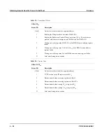
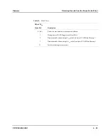
The primary booter contains tools for:
•
Loading software via PCI bus
•
Programming the flash
•
Accessing on-board resources
•
Reporting POST result information to the host
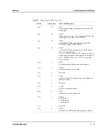
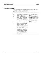
For this purpose a simple communication protocol is implemented. On the follow-
ing pages this communication protocol with its commands, return codes, and the
I/O buffer are described. The end of this section provides instructions on how to
program routines for using the primary booter.
Resources Used by the Primary Booter
As can be seen in the following figure, the primary booter code is located within
the main memory (SDRAM). 256 byte of main memory are used as control and sta-
tus register section (CSR) which is used for the communication protocol. The CSR
section is accessible both from the PCI bus (via the default base translation register
provided by the PCI bridge) and the local PowerQUICC II.
The BST0 register of the PowerSpan II PCI bridge is configured to 4 MByte by
hardware. The primary booter maps this window to the last 4 MByte of local
SDRAM. The PCI memory address is assigned by the PCI bus enumerator of the
host.
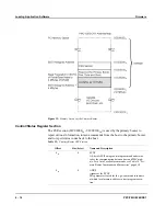
The following figure shows the memory layout as seen from the local CPU (right)
and the PCI bus (left). The SDRAM and SSRAM regions marked by the dashed
lines are not directly accessible from PCI bus. In order to read from/write to these
regions, the contents must first be copied into the I/O buffer area (see shaded area
in the following figure).
Summary of Contents for PPC/PMC-8260/DS1
Page 1: ...PPC PMC 8260 DS1 Reference Guide P N 6806800B10A July 2006 ...
Page 8: ...viii PPC PMC 8260 DS1 ...
Page 22: ...xxii PPC PMC 8260 DS1 ...
Page 26: ...xxvi PPC PMC 8260 DS1 ...
Page 30: ...xxx PPC PMC 8260 DS1 ...
Page 31: ...1 Introduction ...
Page 32: ......
Page 39: ...2 Installation ...
Page 40: ......
Page 53: ...3 Indicators and Connectors ...
Page 54: ......
Page 64: ...On Board Connectors Indicators and Connectors 3 12 PPC PMC 8260 DS1 ...
Page 65: ...4 Firmware ...
Page 66: ......
Page 104: ...Code Examples Firmware 4 40 PPC PMC 8260 DS1 ...
Page 105: ...5 Memory Map and Devices ...
Page 106: ......
Page 132: ...Resetting the Devices Memory Map and Devices 5 28 PPC PMC 8260 DS1 ...
Page 133: ...6 TDM Channel Configuration ...
Page 134: ......
Page 145: ...A Troubleshooting ...
Page 146: ......
Page 148: ...A 4 PPC PMC 8260 DS1 ...
Page 150: ...I 2 PPC PMC 8260 DS1 ...