


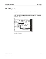


PowerSPAN II PCI Bus Bridge
Memory Map and Devices
5 - 10
PPC/PMC-8260/DS1
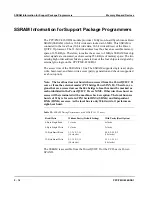
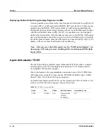
also provides a mechanism for the user to perform master read and write operations
to the E
2
PROM.
The PowerSPAN II reads the first twelve bytes of the serial E
2
PROM during
PCI bus reset to initialize certain registers. This is, for example, the PCI_SID regis-
ter containing the Subsystem Vendor ID, the Subsystem ID or the PBTI0_CTL or
PBTI1_CTL registers containing the block size of the PCI target images and others.
The serial E
2
PROM is not write-protected and its contents can be modified via
PowerSPAN II register EEPROM_CS.
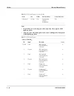
The default contents of the E
2
PROM loaded by the PowerSPAN II are listed in the
table below. For further information on the PowerSPAN II Serial E
2
PROM con-
tents refer to the
PowerSPAN II User Manual
.
Note: The settings printed in bold in the following table must not be modi-
fied. Otherwise, the proper function of the firmware delivered together with
the PPC/PMC-8260/DS1 cannot be guaranteed.
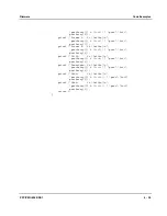
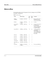
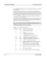
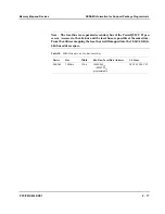
Table 25:
PowerSPAN II Serial E
2
PROM Contents
Byte Offset
Contents
Affected PowerSPAN II Registers
0
01
16
Defines short E
2
PROM data format
1...4
00
16
Reserved
5
0c
16
P1_CSR[BM]: Enable PCI bus master
P1_CSR[MS]: Enable PCI memory space
6
08
16
P1_BST0[PRFTCH]: Target image 0 prefetch enable
7...8
1146
16
P1_SID[SID]: FORCE Computers Vendor ID
9...10
8260
16
P1_SID[SVID]: PMC8260/DS1 assigned subsystem ID
11
02
16
P1_MISC1[INT_PIN[0]]: Interrupt pin enable
12
18
16
P1_MISC_CSR[BSREG_BAR_EN]: Register image BAR
enable
P1_TI0_CTL[BAR_EN]: Target image 0 BAR enable
13
60
16
P1_TI0_CTL[BS]: Target image 0 block size is 4 MByte
14
00
16
P1_TI2_CTL, P1_TI3_CTL: Target image 2 and 3 block size set
to 0
15
00
16
PCI Vital Product Data disabled
16
80
16
MISC_CSR[P1_LOCKOUT]: Clear PCI Lockout after load
Summary of Contents for PPC/PMC-8260/DS1
Page 1: ...PPC PMC 8260 DS1 Reference Guide P N 6806800B10A July 2006 ...
Page 8: ...viii PPC PMC 8260 DS1 ...
Page 22: ...xxii PPC PMC 8260 DS1 ...
Page 26: ...xxvi PPC PMC 8260 DS1 ...
Page 30: ...xxx PPC PMC 8260 DS1 ...
Page 31: ...1 Introduction ...
Page 32: ......
Page 39: ...2 Installation ...
Page 40: ......
Page 53: ...3 Indicators and Connectors ...
Page 54: ......
Page 64: ...On Board Connectors Indicators and Connectors 3 12 PPC PMC 8260 DS1 ...
Page 65: ...4 Firmware ...
Page 66: ......
Page 104: ...Code Examples Firmware 4 40 PPC PMC 8260 DS1 ...
Page 105: ...5 Memory Map and Devices ...
Page 106: ......
Page 132: ...Resetting the Devices Memory Map and Devices 5 28 PPC PMC 8260 DS1 ...
Page 133: ...6 TDM Channel Configuration ...
Page 134: ......
Page 145: ...A Troubleshooting ...
Page 146: ......
Page 148: ...A 4 PPC PMC 8260 DS1 ...
Page 150: ...I 2 PPC PMC 8260 DS1 ...