


Memory Map and Devices
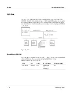
I/O-Bus
PPC/PMC-8260/DS1
5 - 23
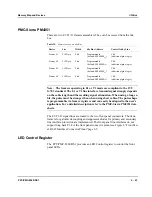
PMC-Sierra PM4351
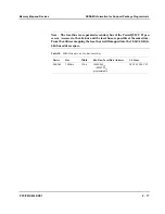
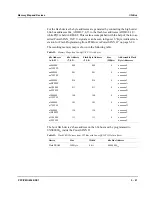
There are two E1/T1/J1 framers assembled. They can be accessed from the 60x
bus.
Table 35:
Framer Access on 60x Bus
Device
Size
Width
60x Bus Address
Controlled by Line
Framer #1
512 Byte
8 bit
Programmable
(default: F0040000
16
)
CS6
(additional glue logic)
Framer #2
512 Byte
8 bit
Programmable
(default: F0040200
16
)
CS6
(additional glue logic)
Framer #3
512 Byte
8 bit
Programmable
(default: F0040400
16
)
CS6
(additional glue logic)
Framer #4
512 Byte
8 bit
Programmable
(default: F0040600
16
)
CS6
(additional glue logic)
Note: The framers operating in E1 or T1 mode are compliant to the ITU
G.703 standard. The E1 or T1 line interface transmit signal strongly depends
on the cable length and the resulting signal attenuation. When using a long ca-
ble, the pulse must be stronger than when using short cables. The pulse shape
is programmable via framer registers and can easily be adapted to the user’s
application. For a detailed description refer to the PMC-Sierra PM4351 data
sheets.
The E1/T1/J1 signal lines are routed to the two front panel connectors. The trans-
formers for galvanic decoupling and suppressor diodes for primary and secondary
line interface protection are implemented. The front panel line interfaces do not
support long haul T1. For the front panel connector pinout see Figure 6 “Front Pan-
el RJ-45 Interface Connector Pinout”page 3-5.
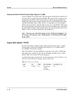
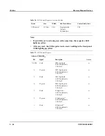
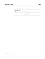
LED Control Register
The PPC/PMC-8260/DS1 provides an LED Control register to control the front
panel LEDs.
Summary of Contents for PPC/PMC-8260/DS1
Page 1: ...PPC PMC 8260 DS1 Reference Guide P N 6806800B10A July 2006 ...
Page 8: ...viii PPC PMC 8260 DS1 ...
Page 22: ...xxii PPC PMC 8260 DS1 ...
Page 26: ...xxvi PPC PMC 8260 DS1 ...
Page 30: ...xxx PPC PMC 8260 DS1 ...
Page 31: ...1 Introduction ...
Page 32: ......
Page 39: ...2 Installation ...
Page 40: ......
Page 53: ...3 Indicators and Connectors ...
Page 54: ......
Page 64: ...On Board Connectors Indicators and Connectors 3 12 PPC PMC 8260 DS1 ...
Page 65: ...4 Firmware ...
Page 66: ......
Page 104: ...Code Examples Firmware 4 40 PPC PMC 8260 DS1 ...
Page 105: ...5 Memory Map and Devices ...
Page 106: ......
Page 132: ...Resetting the Devices Memory Map and Devices 5 28 PPC PMC 8260 DS1 ...
Page 133: ...6 TDM Channel Configuration ...
Page 134: ......
Page 145: ...A Troubleshooting ...
Page 146: ......
Page 148: ...A 4 PPC PMC 8260 DS1 ...
Page 150: ...I 2 PPC PMC 8260 DS1 ...